-
 Agriculture
-
 Health-Care
-
 Environment
-
 Construction-Real-Estate
-
 Tools-Hardware
-
 Home-Garden
-
 Furniture
-
 Luggage-Bags-Cases
-
 Medical-devices-Supplies
-
 Gifts-Crafts
-
 Sports-Entertainment
-
 Food-Beverage
-
 Vehicles-Transportation
-
 Power-Transmission
-
 Material-Handling
-
 Renewable-Energy
-
 Safety
-
 Testing-Instrument-Equipment
-
 Construction-Building-Machinery
-
 Pet-Supplies
-
 Personal-Care-Household-Cleaning
-
 Vehicle-Accessories-Electronics-Tools
-
 School-Office-Supplies
-
 Packaging-Printing
-
 Mother-Kids-Toys
-
 Business-Services
-
 Commercial-Equipment-Machinery
-
 Apparel-Accessories
-
 Security
-
 Shoes-Accessories
-
 Vehicle-Parts-Accessories
-
 Jewelry-Eyewear-Watches-Accessories
-
 Lights-Lighting
-
 Fabric-Textile-Raw-Material
-
 Fabrication-Services
-
 Industrial-Machinery
-
 Consumer-Electronics
-
 Electrical-Equipment-Supplies
-
 Electronic-Components-Accessories-Telecommunications
-
 Home-Appliances
-
 Beauty
-
 Chemicals
-
 Rubber-Plastics
-
 Metals-Alloys
- Masonry Materials
- Curtain Walls & Accessories
- Earthwork Products
- Fireproofing Materials
- Heat Insulation Materials
- Plastic Building Materials
- Building Boards
- Soundproofing Materials
- Timber
- Waterproofing Materials
- Balustrades & Handrails
- Bathroom & Kitchen
- Flooring & Accessories
- Tiles & Accessories
- Door, Window & Accessories
- Fireplaces & Stoves
- Floor Heating Systems & Parts
- Stairs & Stair Parts
- Ceilings
- Elevators & Escalators
- Stone
- Countertops, Vanity Tops & Table Tops
- Mosaics
- Metal Building Materials
- Multifunctional Materials
- Ladders & Scaffoldings
- Mouldings
- Corner Guards
- Decorative Films
- Formwork
- Building & Industrial Glass
- Other Construction & Real Estate
- Wallpapers/Wall panels
- HVAC System & Parts
- Outdoor Facilities
- Prefabricated Buildings
- Festive & Party Supplies
- Bathroom Products
- Household Sundries
- Rain Gear
- Garden Supplies
- Household Cleaning Tools & Accessories
- Lighters & Smoking Accessories
- Home Storage & Organization
- Household Scales
- Smart Home Improvement
- Home Textiles
- Kitchenware
- Drinkware & Accessories
- Dinnerware, Coffee & Wine
- Home Decor
- Golf
- Fitness & Body Building
- Amusement Park Facilities
- Billiards, Board Game,Coin Operated Games
- Musical Instruments
- Outdoor Affordable Luxury Sports
- Camping & Hiking
- Fishing
- Sports Safety&Rehabilitation
- Ball Sports Equipments
- Water Sports
- Winter Sports
- Luxury Travel Equipments
- Sports Shoes, Bags & Accessories
- Cycling
- Other Sports & Entertainment Products
- Artificial Grass&Sports Flooring&Sports Court Equipment
- Scooters
- Food Ingredients
- Honey & Honey Products
- Snacks
- Nuts & Kernels
- Seafood
- Plant & Animal Oil
- Beverages
- Fruit & Vegetable Products
- Frog & Escargot
- Bean Products
- Egg Products
- Dairy Products
- Seasonings & Condiments
- Canned Food
- Instant Food
- Baked Goods
- Other Food & Beverage
- Meat & Poultry
- Confectionery
- Grain Products
- Feminie Care
- Hair Care & Styling
- Body Care
- Hands & Feet Care
- Hygiene Products
- Men's Grooming
- Laundry Cleaning Supplies
- Travel Size & Gift Sets
- Room Deodorizers
- Other Personal Care Products
- Pest Control Products
- Special Household Cleaning
- Floor Cleaning
- Kitchen & Bathroom Cleaning
- Oral Care
- Bath Supplies
- Yellow Pages
- Correction Supplies
- Office Binding Supplies
- Office Cutting Supplies
- Board Erasers
- Office Adhesives & Tapes
- Education Supplies
- Pencil Cases & Bags
- Notebooks & Writing Pads
- File Folder Accessories
- Calendars
- Writing Accessories
- Commercial Office Supplies
- Pencil Sharpeners
- Pens
- Letter Pad/Paper
- Paper Envelopes
- Desk Organizers
- Pencils
- Markers & Highlighters
- Filing Products
- Art Supplies
- Easels
- Badge Holder & Accessories
- Office Paper
- Printer Supplies
- Book Covers
- Other Office & School Supplies
- Stationery Set
- Boards
- Clipboards
- Stamps
- Drafting Supplies
- Stencils
- Electronic Dictionary
- Books
- Map
- Magazines
- Calculators
- Baby & Toddler Toys
- Educational Toys
- Classic Toys
- Dress Up & Pretend Play
- Toy Vehicle
- Stuffed Animals & Plush Toys
- Outdoor Toys & Structures
- Balloons & Accessories
- Baby Food
- Children's Clothing
- Baby Supplies & Products
- Maternity Clothes
- Kids Shoes
- Baby Care
- Novelty & Gag Toys
- Dolls & Accessories
- Puzzle & Games
- Blocks & Model Building Toys
- Toddler Clothing
- Baby Clothing
- Kids' Luggage & Bags
- Arts, Crafts & DIY Toys
- Action & Toy Figures
- Baby Appliances
- Hobbies & Models
- Remote Control Toys
- Promotional Toys
- Pregnancy & Maternity
- Hygiene Products
- Kid's Textile&Bedding
- Novelty & Special Use
- Toy Weapons
- Baby Gifts
- Baby Storage & Organization
- Auto Drive Systems
- ATV/UTV Parts & Accessories
- Marine Parts & Accessories
- Other Auto Parts
- Trailer Parts & Accessories
- Auto Transmission Systems
- Train Parts & Accessories
- Universal Parts
- Railway Parts & Accessories
- Auto Brake Systems
- Aviation Parts & Accessories
- Truck Parts & Accessories
- Auto Suspension Systems
- Auto Lighting Systems
- New Energy Vehicle Parts & Accessories
- Auto Steering Systems
- Wheels, Tires & Accessories
- Bus Parts & Accessories
- Auto Performance Parts
- Cooling System
- Go-Kart & Kart Racer Parts & Accessories
- Air Conditioning Systems
- Heavy Duty Vehicle Parts & Accessories
- Auto Electrical Systems
- Auto Body Systems
- Auto Engine Systems
- Container Parts & Accessories
- Motorcycle Parts & Accessories
- Refrigeration & Heat Exchange Equipment
- Machine Tool Equipment
- Food & Beverage Machinery
- Agricultural Machinery & Equipment
- Apparel & Textile Machinery
- Chemical Machinery
- Packaging Machines
- Paper Production Machinery
- Plastic & Rubber Processing Machinery
- Industrial Robots
- Electronic Products Machinery
- Metal & Metallurgy Machinery
- Woodworking Machinery
- Home Product Manufacturing Machinery
- Machinery Accessories
- Environmental Machinery
- Machinery Service
- Electrical Equipment Manufacturing Machinery
- Industrial Compressors & Parts
- Tobacco & Cigarette Machinery
- Production Line
- Used Industrial Machinery
- Electronics Production Machinery
- Other Machinery & Industrial Equipment
- Camera, Photo & Accessories
- Portable Audio, Video & Accessories
- Television, Home Audio, Video & Accessories
- Video Games & Accessories
- Mobile Phone & Accessories
- Electronic Publications
- Earphone & Headphone & Accessories
- Speakers & Accessories
- Smart Electronics
- TV Receivers & Accessories
- Mobile Phone & Computer Repair Parts
- Chargers, Batteries & Power Supplies
- Used Electronics
- VR, AR, MR Hardware & Software
- Projectors & Presentation Equipments
- Other Consumer Electronics
- Cables & Commonly Used Accessories
- Computer Hardware & Software
- Displays, Signage and Optoelectronics
- Discrete Semiconductors
- Wireless & IoT Module and Products
- Telecommunications
- Connectors, Terminals & Accessories
- Development Boards, Electronic Modules and Kits
- Circuit Protection
- Sensors
- Isolators
- Audio Components and Products
- Integrated Circuits
- Power Supplies
- Relays
- RF, Microwave and RFID
- Electronic Accessories & Supplies
- Passive Components
- PCB & PCBA
- Air Quality Appliances
- Home Appliance Parts
- Heating & Cooling Appliances
- Small Kitchen Appliances
- Laundry Appliances
- Water Heaters
- Water Treatment Appliances
- Refrigerators & Freezers
- Personal Care & Beauty Appliances
- Major Kitchen Appliances
- Cleaning Appliances
- Second-hand Appliances
- Smart Home Appliances
- Other Home Appliances
- Energy Chemicals
- Inorganic Chemicals
- Basic Organic Chemicals
- Agrochemicals
- Admixture & Additives
- Catalysts & Chemical Auxiliary Agents
- Pigments & Dyestuff
- Coating & Paint
- Daily Chemicals
- Polymer
- Organic Intermediate
- Adhesives & Sealants
- Chemical Waste
- Biological Chemical Products
- Surface Treatment Chemicals
- Painting & Coating
- Chemical Reagents
- Flavor & Fragrance
- Non-Explosive Demolition Agents
- Other Chemicals
- Custom Chemical Services
Advanced Multi Layer PCB Design For High Density Interconnect HDI Applications Ensuring Superior Signal Integrity And Thermal Management In Modern Electronics
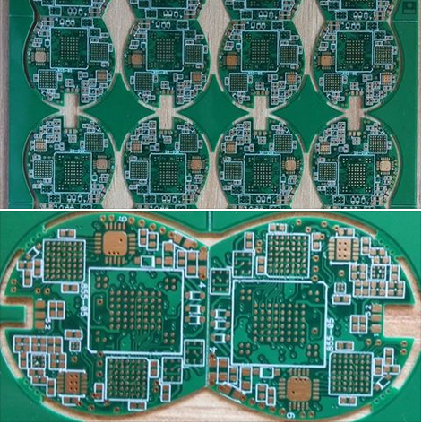
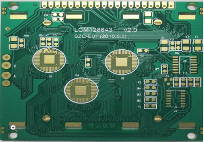
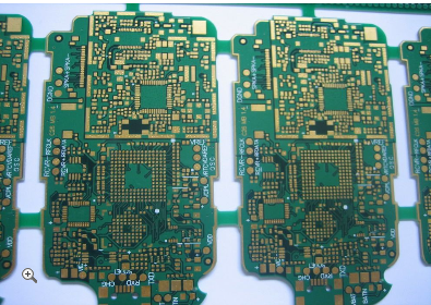
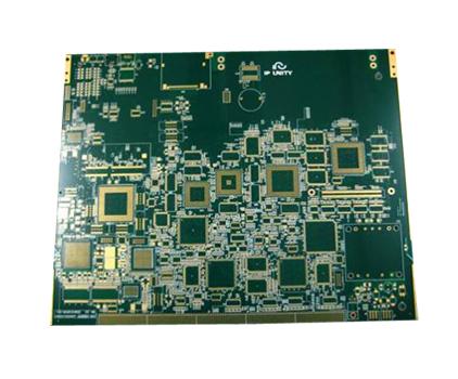
In the relentless march of technological progress, modern electronics are being pushed to unprecedented levels of performance and miniaturization. From the smartphones in our pockets to the servers powering global cloud infrastructure, the demand for more functionality in smaller form factors is insatiable. At the heart of this revolution lies a critical, yet often overlooked, component: the printed circuit board (PCB). The era of simple, double-sided boards is giving way to the age of Advanced Multi-Layer PCB Design for High-Density Interconnect (HDI) applications. This sophisticated engineering discipline is no longer a luxury but a fundamental necessity for ensuring superior signal integrity and effective thermal management in today's high-speed, high-power electronic systems. Without these advanced designs, the next generation of electronics would simply fail to function as intended, plagued by signal degradation, crosstalk, and catastrophic overheating. This article delves into the intricate world of these advanced PCBs, exploring the core principles and techniques that make them the backbone of modern innovation.
The Imperative of High-Density Interconnect (HDI) Technology
The driving force behind advanced multi-layer PCBs is the need for High-Density Interconnect (HDI) technology. Traditional PCB designs, with their larger vias and wider trace spacing, quickly become a bottleneck when attempting to integrate complex System-on-Chips (SoCs), high-pin-count BGAs (Ball Grid Arrays), and dense memory modules. HDI technology overcomes these limitations by utilizing finer lines and spaces, microvias, and sequential lamination processes. This allows for a dramatic increase in the number of interconnections per unit area, effectively creating a more complex "nervous system" for the electronic device.
Key to HDI are microvias, which are laser-drilled holes with diameters typically less than 150 microns. These can be stacked or staggered to create conductive pathways between layers with minimal parasitic inductance and capacitance. The use of blind vias (connecting an outer layer to one or more inner layers) and buried vias (connecting only inner layers) further conserves valuable surface real estate. This architectural freedom enables designers to route complex high-speed buses and escape intricate component patterns that would be impossible with conventional through-hole vias, directly supporting the trend towards ultra-compact and powerful devices.
Ensuring Superior Signal Integrity in High-Speed Designs
As digital signal speeds escalate into the multi-gigahertz range, the PCB itself ceases to be a simple passive carrier and becomes an active component of the signal path. Signal Integrity (SI) is the engineering field concerned with ensuring that these electrical signals are transmitted from a driver to a receiver without significant distortion. In advanced multi-layer HDI PCBs, maintaining SI is a paramount challenge addressed through several critical design strategies.
One of the primary tools for managing SI is controlled impedance. Signals traveling on a PCB trace behave like waves on a transmission line. For optimal power transfer and minimal reflection, the trace's characteristic impedance must match the impedance of the driver and receiver. This is achieved through precise control over the trace width, the dielectric thickness of the PCB material, and its dielectric constant. Advanced design software is used to model and simulate these parameters before fabrication. Furthermore, the strategic use of ground planes in a multi-layer stackup provides a consistent reference for the signal, shields it from external noise, and creates a controlled return path, which is crucial for high-frequency current flow.
Another major SI challenge is crosstalk, where energy from an aggressor signal unintentionally couples onto an adjacent victim trace. HDI designs, with their inherently close proximity of traces, are particularly susceptible. Mitigation techniques include careful spacing of sensitive lines, the use of differential pair routing (where two complementary signals are routed in parallel to reject common-mode noise), and the insertion of ground traces or "guard vias" between critical signal paths. By meticulously managing these factors, designers can preserve the quality of high-speed clocks, data buses, and RF signals, ensuring the reliable operation of the entire system.
Advanced Thermal Management Strategies
The incredible density of components and the high operating speeds of modern electronics generate substantial amounts of heat. If this thermal energy is not effectively managed, it can lead to premature component failure, performance throttling, and reduced product lifespan. Advanced multi-layer PCBs are integral to the thermal management solution, moving beyond simple copper pours to sophisticated, integrated cooling techniques.
The foundation of PCB-level thermal management is the use of thermal vias. These are arrays of plated through-holes placed directly under or near heat-generating components, such as processors or power amplifiers. Thermal vias conduct heat from the surface layer down into the inner ground planes or to a dedicated thermal layer, effectively spreading the heat across a larger area of the board. This reduces the thermal resistance between the component and the board, allowing heat to be more efficiently dissipated into the surrounding air or transferred to an external heatsink.
For the most demanding applications, such as high-performance computing and power electronics, more advanced solutions are employed. Some designs incorporate thick copper layers (e.g., 2oz to 4oz) on inner layers specifically for heat spreading. In extreme cases, metal-core PCBs (MCPCBs) or insulated metal substrates (IMS) are used, where a base material like aluminum acts as a massive heatsink. Another cutting-edge approach involves embedding discrete components, and even passive thermal materials, within the inner layers of the PCB (EDC - Embedded Discrete Components), which can shorten thermal paths and further increase component density. These integrated thermal strategies are essential for maintaining junction temperatures within safe operating limits.
Material Selection and Stackup Planning
The performance of an advanced HDI PCB is profoundly influenced by the materials from which it is constructed and the arrangement of its layers, known as the stackup. The choice of dielectric material moves beyond standard FR-4 to high-performance laminates with carefully engineered electrical and thermal properties.
For high-speed digital and RF applications, materials with a low and stable dielectric constant (Dk) are selected to minimize signal propagation delay and maintain consistent impedance. A low dissipation factor (Df) is equally critical, as it reduces the dielectric losses that attenuate high-frequency signals over distance. Materials like Rogers, Isola, and Panasonic's Megtron series are popular choices for these demanding scenarios. From a thermal perspective, materials with a high Thermal Conductivity (TC) and a high Glass Transition Temperature (Tg) are preferred to withstand the heat of both assembly processes and operational loads.
The stackup plan is a strategic blueprint that defines the number of layers, their sequence (signal, ground, power), and the dielectric thickness between them. A well-designed stackup is fundamental for achieving both signal integrity and power integrity. It ensures a tight coupling between signal layers and their adjacent reference planes, provides a low-inductance path for return currents, and creates a distributed capacitance that helps stabilize the power delivery network (PDN). A poor stackup, on the other hand, can doom a design from the start, leading to uncontrollable EMI, power rail noise, and signal integrity issues that are nearly impossible to fix post-layout.
The Critical Role of Design for Manufacturing (DFM)
The complexity of advanced multi-layer HDI PCBs necessitates a seamless bridge between design intent and manufacturing reality. This is where Design for Manufacturing (DFM) principles become non-negotiable. A design that looks perfect in simulation can be unmanufacturable or yield poorly if DFM rules are ignored, leading to costly delays and re-spins.
Close collaboration with the PCB fabricator from the early stages of design is crucial. Fabricators provide specific guidelines on their capabilities, such as minimum trace width and spacing, minimum microvia size and aspect ratio, copper-to-edge clearance, and lamination sequence. Adhering to these constraints ensures that the design can be reliably produced. For instance, the aspect ratio of a via (board thickness divided by drill diameter) must be within the fabricator's plating capability to ensure a uniform copper barrel is formed inside the hole.
Furthermore, thermal management during the assembly process must be considered. The complex multi-layer stackups can act as significant thermal masses, making it challenging to achieve a uniform temperature profile during solder reflow. This requires careful planning of the reflow profile to avoid defects like cold solder joints or delamination. By integrating DFM checks throughout the design process, engineers can create sophisticated PCBs that are not only high-performing but also robust, reliable, and cost-effective to produce in volume.
REPORT


