-
 Agriculture
-
 Health-Care
-
 Environment
-
 Construction-Real-Estate
-
 Tools-Hardware
-
 Home-Garden
-
 Furniture
-
 Luggage-Bags-Cases
-
 Medical-devices-Supplies
-
 Gifts-Crafts
-
 Sports-Entertainment
-
 Food-Beverage
-
 Vehicles-Transportation
-
 Power-Transmission
-
 Material-Handling
-
 Renewable-Energy
-
 Safety
-
 Testing-Instrument-Equipment
-
 Construction-Building-Machinery
-
 Pet-Supplies
-
 Personal-Care-Household-Cleaning
-
 Vehicle-Accessories-Electronics-Tools
-
 School-Office-Supplies
-
 Packaging-Printing
-
 Mother-Kids-Toys
-
 Business-Services
-
 Commercial-Equipment-Machinery
-
 Apparel-Accessories
-
 Security
-
 Shoes-Accessories
-
 Vehicle-Parts-Accessories
-
 Jewelry-Eyewear-Watches-Accessories
-
 Lights-Lighting
-
 Fabric-Textile-Raw-Material
-
 Fabrication-Services
-
 Industrial-Machinery
-
 Consumer-Electronics
-
 Electrical-Equipment-Supplies
-
 Electronic-Components-Accessories-Telecommunications
-
 Home-Appliances
-
 Beauty
-
 Chemicals
-
 Rubber-Plastics
-
 Metals-Alloys
- Masonry Materials
- Curtain Walls & Accessories
- Earthwork Products
- Fireproofing Materials
- Heat Insulation Materials
- Plastic Building Materials
- Building Boards
- Soundproofing Materials
- Timber
- Waterproofing Materials
- Balustrades & Handrails
- Bathroom & Kitchen
- Flooring & Accessories
- Tiles & Accessories
- Door, Window & Accessories
- Fireplaces & Stoves
- Floor Heating Systems & Parts
- Stairs & Stair Parts
- Ceilings
- Elevators & Escalators
- Stone
- Countertops, Vanity Tops & Table Tops
- Mosaics
- Metal Building Materials
- Multifunctional Materials
- Ladders & Scaffoldings
- Mouldings
- Corner Guards
- Decorative Films
- Formwork
- Building & Industrial Glass
- Other Construction & Real Estate
- Wallpapers/Wall panels
- HVAC System & Parts
- Outdoor Facilities
- Prefabricated Buildings
- Festive & Party Supplies
- Bathroom Products
- Household Sundries
- Rain Gear
- Garden Supplies
- Household Cleaning Tools & Accessories
- Lighters & Smoking Accessories
- Home Storage & Organization
- Household Scales
- Smart Home Improvement
- Home Textiles
- Kitchenware
- Drinkware & Accessories
- Dinnerware, Coffee & Wine
- Home Decor
- Golf
- Fitness & Body Building
- Amusement Park Facilities
- Billiards, Board Game,Coin Operated Games
- Musical Instruments
- Outdoor Affordable Luxury Sports
- Camping & Hiking
- Fishing
- Sports Safety&Rehabilitation
- Ball Sports Equipments
- Water Sports
- Winter Sports
- Luxury Travel Equipments
- Sports Shoes, Bags & Accessories
- Cycling
- Other Sports & Entertainment Products
- Artificial Grass&Sports Flooring&Sports Court Equipment
- Scooters
- Food Ingredients
- Honey & Honey Products
- Snacks
- Nuts & Kernels
- Seafood
- Plant & Animal Oil
- Beverages
- Fruit & Vegetable Products
- Frog & Escargot
- Bean Products
- Egg Products
- Dairy Products
- Seasonings & Condiments
- Canned Food
- Instant Food
- Baked Goods
- Other Food & Beverage
- Meat & Poultry
- Confectionery
- Grain Products
- Feminie Care
- Hair Care & Styling
- Body Care
- Hands & Feet Care
- Hygiene Products
- Men's Grooming
- Laundry Cleaning Supplies
- Travel Size & Gift Sets
- Room Deodorizers
- Other Personal Care Products
- Pest Control Products
- Special Household Cleaning
- Floor Cleaning
- Kitchen & Bathroom Cleaning
- Oral Care
- Bath Supplies
- Yellow Pages
- Correction Supplies
- Office Binding Supplies
- Office Cutting Supplies
- Board Erasers
- Office Adhesives & Tapes
- Education Supplies
- Pencil Cases & Bags
- Notebooks & Writing Pads
- File Folder Accessories
- Calendars
- Writing Accessories
- Commercial Office Supplies
- Pencil Sharpeners
- Pens
- Letter Pad/Paper
- Paper Envelopes
- Desk Organizers
- Pencils
- Markers & Highlighters
- Filing Products
- Art Supplies
- Easels
- Badge Holder & Accessories
- Office Paper
- Printer Supplies
- Book Covers
- Other Office & School Supplies
- Stationery Set
- Boards
- Clipboards
- Stamps
- Drafting Supplies
- Stencils
- Electronic Dictionary
- Books
- Map
- Magazines
- Calculators
- Baby & Toddler Toys
- Educational Toys
- Classic Toys
- Dress Up & Pretend Play
- Toy Vehicle
- Stuffed Animals & Plush Toys
- Outdoor Toys & Structures
- Balloons & Accessories
- Baby Food
- Children's Clothing
- Baby Supplies & Products
- Maternity Clothes
- Kids Shoes
- Baby Care
- Novelty & Gag Toys
- Dolls & Accessories
- Puzzle & Games
- Blocks & Model Building Toys
- Toddler Clothing
- Baby Clothing
- Kids' Luggage & Bags
- Arts, Crafts & DIY Toys
- Action & Toy Figures
- Baby Appliances
- Hobbies & Models
- Remote Control Toys
- Promotional Toys
- Pregnancy & Maternity
- Hygiene Products
- Kid's Textile&Bedding
- Novelty & Special Use
- Toy Weapons
- Baby Gifts
- Baby Storage & Organization
- Auto Drive Systems
- ATV/UTV Parts & Accessories
- Marine Parts & Accessories
- Other Auto Parts
- Trailer Parts & Accessories
- Auto Transmission Systems
- Train Parts & Accessories
- Universal Parts
- Railway Parts & Accessories
- Auto Brake Systems
- Aviation Parts & Accessories
- Truck Parts & Accessories
- Auto Suspension Systems
- Auto Lighting Systems
- New Energy Vehicle Parts & Accessories
- Auto Steering Systems
- Wheels, Tires & Accessories
- Bus Parts & Accessories
- Auto Performance Parts
- Cooling System
- Go-Kart & Kart Racer Parts & Accessories
- Air Conditioning Systems
- Heavy Duty Vehicle Parts & Accessories
- Auto Electrical Systems
- Auto Body Systems
- Auto Engine Systems
- Container Parts & Accessories
- Motorcycle Parts & Accessories
- Refrigeration & Heat Exchange Equipment
- Machine Tool Equipment
- Food & Beverage Machinery
- Agricultural Machinery & Equipment
- Apparel & Textile Machinery
- Chemical Machinery
- Packaging Machines
- Paper Production Machinery
- Plastic & Rubber Processing Machinery
- Industrial Robots
- Electronic Products Machinery
- Metal & Metallurgy Machinery
- Woodworking Machinery
- Home Product Manufacturing Machinery
- Machinery Accessories
- Environmental Machinery
- Machinery Service
- Electrical Equipment Manufacturing Machinery
- Industrial Compressors & Parts
- Tobacco & Cigarette Machinery
- Production Line
- Used Industrial Machinery
- Electronics Production Machinery
- Other Machinery & Industrial Equipment
- Camera, Photo & Accessories
- Portable Audio, Video & Accessories
- Television, Home Audio, Video & Accessories
- Video Games & Accessories
- Mobile Phone & Accessories
- Electronic Publications
- Earphone & Headphone & Accessories
- Speakers & Accessories
- Smart Electronics
- TV Receivers & Accessories
- Mobile Phone & Computer Repair Parts
- Chargers, Batteries & Power Supplies
- Used Electronics
- VR, AR, MR Hardware & Software
- Projectors & Presentation Equipments
- Other Consumer Electronics
- Cables & Commonly Used Accessories
- Computer Hardware & Software
- Displays, Signage and Optoelectronics
- Discrete Semiconductors
- Wireless & IoT Module and Products
- Telecommunications
- Connectors, Terminals & Accessories
- Development Boards, Electronic Modules and Kits
- Circuit Protection
- Sensors
- Isolators
- Audio Components and Products
- Integrated Circuits
- Power Supplies
- Relays
- RF, Microwave and RFID
- Electronic Accessories & Supplies
- Passive Components
- PCB & PCBA
- Air Quality Appliances
- Home Appliance Parts
- Heating & Cooling Appliances
- Small Kitchen Appliances
- Laundry Appliances
- Water Heaters
- Water Treatment Appliances
- Refrigerators & Freezers
- Personal Care & Beauty Appliances
- Major Kitchen Appliances
- Cleaning Appliances
- Second-hand Appliances
- Smart Home Appliances
- Other Home Appliances
- Energy Chemicals
- Inorganic Chemicals
- Basic Organic Chemicals
- Agrochemicals
- Admixture & Additives
- Catalysts & Chemical Auxiliary Agents
- Pigments & Dyestuff
- Coating & Paint
- Daily Chemicals
- Polymer
- Organic Intermediate
- Adhesives & Sealants
- Chemical Waste
- Biological Chemical Products
- Surface Treatment Chemicals
- Painting & Coating
- Chemical Reagents
- Flavor & Fragrance
- Non-Explosive Demolition Agents
- Other Chemicals
- Custom Chemical Services
Exploring The Complex Process Of Multilayer PCB Fabrication From Design To Final Product Assembly
In the intricate world of modern electronics, multilayer printed circuit boards (PCBs) stand as the backbone of countless devices, from smartphones and computers to medical equipment and automotive systems. The journey from a conceptual design to a fully assembled, functional multilayer PCB is a marvel of engineering precision and technological innovation. This process involves numerous stages, each demanding meticulous attention to detail to ensure reliability, performance, and efficiency. As technology advances, the complexity of these boards has grown, with some featuring over 50 layers, pushing the boundaries of what's possible in miniaturization and connectivity. By exploring the multilayer PCB fabrication process, we uncover the fascinating interplay of design, material science, and manufacturing that brings cutting-edge electronics to life. Whether you're an engineer, a student, or simply curious about how your gadgets work, this deep dive will provide valuable insights into the hidden world behind every click, swipe, and beep.
Design and Prototyping
The journey of multilayer PCB fabrication begins with design, a critical phase where engineers translate ideas into detailed schematics and layouts. Using specialized software like Altium Designer or Eagle, designers create a virtual blueprint that defines the board's electrical connections, component placement, and layer stack-up. This stage involves careful consideration of factors such as signal integrity, power distribution, and thermal management to avoid issues like crosstalk or overheating. Designers must adhere to industry standards and manufacturer guidelines to ensure the board can be produced efficiently. For multilayer PCBs, this includes planning the inner layers, which are not visible in the final product but are essential for routing complex circuits. Once the design is complete, it undergoes a design rule check (DRC) to identify any errors or inconsistencies that could lead to fabrication failures.
After the initial design, prototyping plays a vital role in validating the concept before full-scale production. Prototypes are often created using rapid prototyping techniques, such as 3D printing or small-batch manufacturing, to test functionality and performance. This step allows engineers to identify and rectify design flaws early, saving time and costs in the long run. For instance, they might adjust trace widths or via placements to optimize signal flow. Feedback from prototyping is integrated into the design, leading to iterative improvements until the board meets all specifications. This phase is crucial for multilayer PCBs, as the interplay between layers can introduce unique challenges, such as impedance mismatches or electromagnetic interference. By refining the design through prototyping, manufacturers ensure that the final product will perform reliably in real-world applications.
Material Selection and Layer Preparation
Material selection is a foundational aspect of multilayer PCB fabrication, as it directly impacts the board's durability, electrical properties, and overall performance. The core material is typically a substrate like FR-4, a flame-retardant fiberglass epoxy laminate, chosen for its balance of cost, strength, and insulation properties. For high-frequency applications, materials such as Rogers or Teflon might be used to minimize signal loss. Copper foil is laminated onto the substrate to form conductive layers, with thickness varying based on current-carrying requirements. In multilayer boards, prepreg—a partially cured epoxy resin—acts as an adhesive between layers, ensuring a solid bond during lamination. The choice of materials must align with the board's intended environment, such as resistance to moisture or high temperatures, to prevent failures in demanding conditions.
Once materials are selected, the layer preparation process begins, starting with the inner layers. Each inner layer is coated with a photosensitive film and exposed to UV light through a photomask, which transfers the circuit pattern from the design files. After exposure, the unexposed areas are etched away, leaving behind the copper traces that form the electrical pathways. This step requires precision, as any misalignment can lead to short circuits or open connections in the final board. The prepared inner layers are then inspected using automated optical inspection (AOI) systems to detect defects like scratches or incomplete etching. This quality control measure is essential for multilayer PCBs, where inner layer errors are difficult to correct once the board is assembled. By ensuring each layer is flawless, manufacturers lay the groundwork for a reliable multilayer structure.
Lamination and Drilling
Lamination is where the individual layers of a multilayer PCB are bonded together under heat and pressure to form a single, cohesive unit. The process starts by stacking the inner layers, prepreg sheets, and outer copper layers in a precise sequence, as defined in the design. This stack is placed into a lamination press, where it undergoes a controlled heating cycle to cure the prepreg, creating a solid, insulating core. Pressure is applied to eliminate air pockets and ensure uniform adhesion, which is critical for preventing delamination—a common failure in multilayer boards. The temperature and pressure parameters are carefully calibrated based on the materials used, as variations can affect the board's electrical and mechanical properties. Once laminated, the board is cooled and trimmed to its final dimensions, ready for the next stages of fabrication.
After lamination, drilling is performed to create vias—small holes that facilitate electrical connections between layers. This step uses computer-controlled drills with high precision to bore holes at exact locations specified in the design. For multilayer PCBs, various types of vias are employed, such as through-hole vias that span the entire board, blind vias that connect an outer layer to an inner layer, and buried vias that link inner layers without reaching the surface. The drilling process must account for factors like hole size and aspect ratio to avoid issues like drill breakage or misalignment. Following drilling, the holes are deburred and cleaned to remove any residue, ensuring a smooth surface for subsequent plating. This stage is vital for establishing the interlayer connectivity that defines multilayer PCBs, enabling complex circuit designs in a compact form factor.
Plating and Outer Layer Processing
Plating is a key step in multilayer PCB fabrication, as it metallizes the drilled vias and outer layers to establish conductive pathways. The process begins with electrodes copper plating, where a thin layer of copper is deposited onto the walls of the holes through a chemical reaction. This creates a base for subsequent electroplating, which builds up a thicker copper layer to ensure reliable electrical connections. The entire board may then be plated with additional metals, such as tin or gold, to enhance conductivity and protect against oxidation. For multilayer PCBs, plating must be uniform across all layers to prevent signal loss or intermittent connections. Advanced techniques like pulse plating are sometimes used to improve copper distribution in high-aspect-ratio vias, which are common in dense designs.
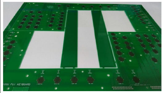
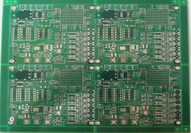
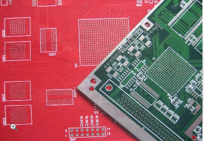
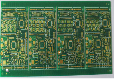
After plating, the outer layers undergo patterning similar to the inner layers, using photoresist and etching to define the final circuit traces. A solder mask is applied to protect the copper from environmental damage and prevent solder bridges during assembly. This mask is typically green or another color, and it is cured under UV light after being applied through a silkscreen process. Following this, a silkscreen layer is added to print component labels, logos, and other identifiers on the board surface. Finally, surface finishes like HASL (Hot Air Solder Leveling), ENIG (Electroless Nickel Immersion Gold), or OSP (Organic Solderability Preservative) are applied to ensure solderability and longevity. Each finish has its advantages; for example, ENIG provides a flat surface for fine-pitch components, while HASL is cost-effective for general applications. This stage completes the fabrication of the bare PCB, setting the stage for component assembly.
Final Product Assembly and Testing
The assembly phase transforms the fabricated multilayer PCB into a functional electronic product by mounting components onto the board. This begins with solder paste application, where a stencil is used to deposit paste onto the solder pads. Components are then placed accurately using automated pick-and-place machines, which handle everything from tiny resistors to complex integrated circuits. The board proceeds to reflow soldering, where it passes through an oven that melts the solder paste, creating permanent electrical and mechanical bonds. For through-hole components, wave soldering or manual soldering might be employed. In multilayer PCBs, assembly must account for thermal management to prevent damage to inner layers, and techniques like thermal profiling ensure even heating across the board.
After assembly, rigorous testing is conducted to verify the board's functionality and reliability. In-circuit testing (ICT) checks for shorts, opens, and component values by probing specific test points on the board. Functional testing simulates real-world operating conditions to ensure the PCB performs as intended in its final application. For high-reliability products, environmental stress testing, such as thermal cycling or vibration tests, may be performed to validate durability. Any defects identified during testing lead to rework or troubleshooting, which might involve replacing faulty components or repairing traces. Once the board passes all tests, it is cleaned to remove flux residues and prepared for integration into the end product, such as a smartphone or medical device. This final step closes the loop on the multilayer PCB fabrication process, delivering a high-quality component ready to power innovation.
REPORT


