-
 Agriculture
-
 Health-Care
-
 Environment
-
 Construction-Real-Estate
-
 Tools-Hardware
-
 Home-Garden
-
 Furniture
-
 Luggage-Bags-Cases
-
 Medical-devices-Supplies
-
 Gifts-Crafts
-
 Sports-Entertainment
-
 Food-Beverage
-
 Vehicles-Transportation
-
 Power-Transmission
-
 Material-Handling
-
 Renewable-Energy
-
 Safety
-
 Testing-Instrument-Equipment
-
 Construction-Building-Machinery
-
 Pet-Supplies
-
 Personal-Care-Household-Cleaning
-
 Vehicle-Accessories-Electronics-Tools
-
 School-Office-Supplies
-
 Packaging-Printing
-
 Mother-Kids-Toys
-
 Business-Services
-
 Commercial-Equipment-Machinery
-
 Apparel-Accessories
-
 Security
-
 Shoes-Accessories
-
 Vehicle-Parts-Accessories
-
 Jewelry-Eyewear-Watches-Accessories
-
 Lights-Lighting
-
 Fabric-Textile-Raw-Material
-
 Fabrication-Services
-
 Industrial-Machinery
-
 Consumer-Electronics
-
 Electrical-Equipment-Supplies
-
 Electronic-Components-Accessories-Telecommunications
-
 Home-Appliances
-
 Beauty
-
 Chemicals
-
 Rubber-Plastics
-
 Metals-Alloys
- Masonry Materials
- Curtain Walls & Accessories
- Earthwork Products
- Fireproofing Materials
- Heat Insulation Materials
- Plastic Building Materials
- Building Boards
- Soundproofing Materials
- Timber
- Waterproofing Materials
- Balustrades & Handrails
- Bathroom & Kitchen
- Flooring & Accessories
- Tiles & Accessories
- Door, Window & Accessories
- Fireplaces & Stoves
- Floor Heating Systems & Parts
- Stairs & Stair Parts
- Ceilings
- Elevators & Escalators
- Stone
- Countertops, Vanity Tops & Table Tops
- Mosaics
- Metal Building Materials
- Multifunctional Materials
- Ladders & Scaffoldings
- Mouldings
- Corner Guards
- Decorative Films
- Formwork
- Building & Industrial Glass
- Other Construction & Real Estate
- Wallpapers/Wall panels
- HVAC System & Parts
- Outdoor Facilities
- Prefabricated Buildings
- Festive & Party Supplies
- Bathroom Products
- Household Sundries
- Rain Gear
- Garden Supplies
- Household Cleaning Tools & Accessories
- Lighters & Smoking Accessories
- Home Storage & Organization
- Household Scales
- Smart Home Improvement
- Home Textiles
- Kitchenware
- Drinkware & Accessories
- Dinnerware, Coffee & Wine
- Home Decor
- Golf
- Fitness & Body Building
- Amusement Park Facilities
- Billiards, Board Game,Coin Operated Games
- Musical Instruments
- Outdoor Affordable Luxury Sports
- Camping & Hiking
- Fishing
- Sports Safety&Rehabilitation
- Ball Sports Equipments
- Water Sports
- Winter Sports
- Luxury Travel Equipments
- Sports Shoes, Bags & Accessories
- Cycling
- Other Sports & Entertainment Products
- Artificial Grass&Sports Flooring&Sports Court Equipment
- Scooters
- Food Ingredients
- Honey & Honey Products
- Snacks
- Nuts & Kernels
- Seafood
- Plant & Animal Oil
- Beverages
- Fruit & Vegetable Products
- Frog & Escargot
- Bean Products
- Egg Products
- Dairy Products
- Seasonings & Condiments
- Canned Food
- Instant Food
- Baked Goods
- Other Food & Beverage
- Meat & Poultry
- Confectionery
- Grain Products
- Feminie Care
- Hair Care & Styling
- Body Care
- Hands & Feet Care
- Hygiene Products
- Men's Grooming
- Laundry Cleaning Supplies
- Travel Size & Gift Sets
- Room Deodorizers
- Other Personal Care Products
- Pest Control Products
- Special Household Cleaning
- Floor Cleaning
- Kitchen & Bathroom Cleaning
- Oral Care
- Bath Supplies
- Yellow Pages
- Correction Supplies
- Office Binding Supplies
- Office Cutting Supplies
- Board Erasers
- Office Adhesives & Tapes
- Education Supplies
- Pencil Cases & Bags
- Notebooks & Writing Pads
- File Folder Accessories
- Calendars
- Writing Accessories
- Commercial Office Supplies
- Pencil Sharpeners
- Pens
- Letter Pad/Paper
- Paper Envelopes
- Desk Organizers
- Pencils
- Markers & Highlighters
- Filing Products
- Art Supplies
- Easels
- Badge Holder & Accessories
- Office Paper
- Printer Supplies
- Book Covers
- Other Office & School Supplies
- Stationery Set
- Boards
- Clipboards
- Stamps
- Drafting Supplies
- Stencils
- Electronic Dictionary
- Books
- Map
- Magazines
- Calculators
- Baby & Toddler Toys
- Educational Toys
- Classic Toys
- Dress Up & Pretend Play
- Toy Vehicle
- Stuffed Animals & Plush Toys
- Outdoor Toys & Structures
- Balloons & Accessories
- Baby Food
- Children's Clothing
- Baby Supplies & Products
- Maternity Clothes
- Kids Shoes
- Baby Care
- Novelty & Gag Toys
- Dolls & Accessories
- Puzzle & Games
- Blocks & Model Building Toys
- Toddler Clothing
- Baby Clothing
- Kids' Luggage & Bags
- Arts, Crafts & DIY Toys
- Action & Toy Figures
- Baby Appliances
- Hobbies & Models
- Remote Control Toys
- Promotional Toys
- Pregnancy & Maternity
- Hygiene Products
- Kid's Textile&Bedding
- Novelty & Special Use
- Toy Weapons
- Baby Gifts
- Baby Storage & Organization
- Auto Drive Systems
- ATV/UTV Parts & Accessories
- Marine Parts & Accessories
- Other Auto Parts
- Trailer Parts & Accessories
- Auto Transmission Systems
- Train Parts & Accessories
- Universal Parts
- Railway Parts & Accessories
- Auto Brake Systems
- Aviation Parts & Accessories
- Truck Parts & Accessories
- Auto Suspension Systems
- Auto Lighting Systems
- New Energy Vehicle Parts & Accessories
- Auto Steering Systems
- Wheels, Tires & Accessories
- Bus Parts & Accessories
- Auto Performance Parts
- Cooling System
- Go-Kart & Kart Racer Parts & Accessories
- Air Conditioning Systems
- Heavy Duty Vehicle Parts & Accessories
- Auto Electrical Systems
- Auto Body Systems
- Auto Engine Systems
- Container Parts & Accessories
- Motorcycle Parts & Accessories
- Refrigeration & Heat Exchange Equipment
- Machine Tool Equipment
- Food & Beverage Machinery
- Agricultural Machinery & Equipment
- Apparel & Textile Machinery
- Chemical Machinery
- Packaging Machines
- Paper Production Machinery
- Plastic & Rubber Processing Machinery
- Industrial Robots
- Electronic Products Machinery
- Metal & Metallurgy Machinery
- Woodworking Machinery
- Home Product Manufacturing Machinery
- Machinery Accessories
- Environmental Machinery
- Machinery Service
- Electrical Equipment Manufacturing Machinery
- Industrial Compressors & Parts
- Tobacco & Cigarette Machinery
- Production Line
- Used Industrial Machinery
- Electronics Production Machinery
- Other Machinery & Industrial Equipment
- Camera, Photo & Accessories
- Portable Audio, Video & Accessories
- Television, Home Audio, Video & Accessories
- Video Games & Accessories
- Mobile Phone & Accessories
- Electronic Publications
- Earphone & Headphone & Accessories
- Speakers & Accessories
- Smart Electronics
- TV Receivers & Accessories
- Mobile Phone & Computer Repair Parts
- Chargers, Batteries & Power Supplies
- Used Electronics
- VR, AR, MR Hardware & Software
- Projectors & Presentation Equipments
- Other Consumer Electronics
- Cables & Commonly Used Accessories
- Computer Hardware & Software
- Displays, Signage and Optoelectronics
- Discrete Semiconductors
- Wireless & IoT Module and Products
- Telecommunications
- Connectors, Terminals & Accessories
- Development Boards, Electronic Modules and Kits
- Circuit Protection
- Sensors
- Isolators
- Audio Components and Products
- Integrated Circuits
- Power Supplies
- Relays
- RF, Microwave and RFID
- Electronic Accessories & Supplies
- Passive Components
- PCB & PCBA
- Air Quality Appliances
- Home Appliance Parts
- Heating & Cooling Appliances
- Small Kitchen Appliances
- Laundry Appliances
- Water Heaters
- Water Treatment Appliances
- Refrigerators & Freezers
- Personal Care & Beauty Appliances
- Major Kitchen Appliances
- Cleaning Appliances
- Second-hand Appliances
- Smart Home Appliances
- Other Home Appliances
- Energy Chemicals
- Inorganic Chemicals
- Basic Organic Chemicals
- Agrochemicals
- Admixture & Additives
- Catalysts & Chemical Auxiliary Agents
- Pigments & Dyestuff
- Coating & Paint
- Daily Chemicals
- Polymer
- Organic Intermediate
- Adhesives & Sealants
- Chemical Waste
- Biological Chemical Products
- Surface Treatment Chemicals
- Painting & Coating
- Chemical Reagents
- Flavor & Fragrance
- Non-Explosive Demolition Agents
- Other Chemicals
- Custom Chemical Services
Exploring The Intricate World Of Mechanical Blind Hole PCB Design And Manufacturing
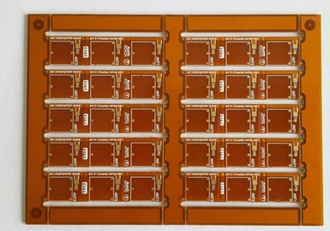
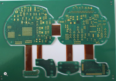
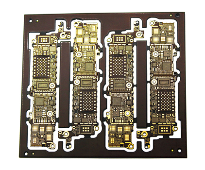
In the rapidly evolving landscape of electronics, the demand for compact, high-performance devices has driven innovations in printed circuit board (PCB) technology. Among these advancements, mechanical blind hole PCBs stand out as a critical solution for complex multilayer designs, enabling enhanced functionality in space-constrained applications like smartphones, medical implants, and aerospace systems. Unlike traditional through-hole vias that span the entire board thickness, blind holes are drilled to a specific depth, connecting outer layers to inner ones without penetrating the opposite side. This intricate approach not only saves valuable real estate but also improves signal integrity by reducing parasitic capacitance and inductance. As industries push for miniaturization and higher density interconnects, understanding the design and manufacturing nuances of mechanical blind holes becomes essential for engineers and manufacturers aiming to stay competitive. This article delves into the fascinating world of these specialized PCBs, exploring their fundamental principles, design challenges, manufacturing processes, and future trends, providing readers with a comprehensive overview of how they shape modern electronics.
Fundamentals of Mechanical Blind Holes
Mechanical blind holes are a type of via used in PCBs to create electrical connections between the outer layer and one or more inner layers, without extending through the entire board. They are typically formed using precision drilling techniques, such as laser drilling or mechanical drilling with controlled depth, which allows for accurate targeting of specific layers. This contrasts with through-hole vias, which pass from the top to the bottom layer, and buried vias, which are entirely contained within the inner layers. The primary advantage of blind holes lies in their ability to conserve space on the PCB, as they do not occupy area on the opposite side, thereby enabling higher component density and more efficient routing in multilayer boards.
In terms of electrical performance, blind holes offer significant benefits by minimizing signal path lengths and reducing the risk of crosstalk and electromagnetic interference. This is particularly crucial in high-frequency applications, such as RF circuits and high-speed digital systems, where signal integrity is paramount. Additionally, blind holes can enhance thermal management by allowing better heat dissipation through targeted layer connections. However, their implementation requires careful consideration of factors like aspect ratio—the ratio of hole depth to diameter—as higher aspect ratios can pose challenges in plating and reliability. Overall, mastering the fundamentals of mechanical blind holes is the first step toward leveraging their potential in advanced PCB designs.
Design Considerations and Challenges
Designing PCBs with mechanical blind holes involves a meticulous approach to ensure functionality and manufacturability. One key consideration is the selection of appropriate materials, as the substrate must withstand the stresses of drilling and plating without delamination or cracking. For instance, materials like FR-4, high-Tg laminates, or polyimide are commonly used, depending on the application's thermal and mechanical requirements. Designers must also account for the aspect ratio, typically keeping it below 1:1 to facilitate reliable plating and avoid voids that could compromise electrical connections. Moreover, the placement of blind holes relative to other features, such as components and traces, requires precise alignment to prevent short circuits or signal degradation.
Another major challenge in blind hole design is managing signal integrity and impedance control. Since blind holes introduce discontinuities in the transmission lines, simulations using tools like electromagnetic field solvers are essential to predict and mitigate reflections or losses. Thermal management is also critical, as uneven heat distribution during operation or manufacturing can lead to failures like pad lifting or hole wall cracking. To address these issues, designers often employ design for manufacturability (DFM) principles, collaborating closely with manufacturers to optimize parameters such as drill size, plating thickness, and layer stack-up. By anticipating these challenges early in the design phase, engineers can create robust PCBs that meet performance and reliability standards.
Manufacturing Processes and Techniques
The manufacturing of mechanical blind hole PCBs is a multi-step process that demands precision and advanced equipment. It typically begins with layer preparation, where copper-clad laminates are cleaned and treated to ensure adhesion. Next, controlled-depth drilling is performed using specialized machines, such as CNC drills or laser systems, which can achieve micron-level accuracy. Laser drilling is particularly favored for its ability to create small-diameter holes with high aspect ratios, though it requires careful parameter tuning to avoid thermal damage to the surrounding material. After drilling, the holes undergo desmearing to remove resin residues, followed by electrodes copper plating to establish a conductive layer on the hole walls.
Subsequent steps include pattern plating to build up the copper thickness and ensure reliable electrical connections, as well as lamination to bond the layers into a single board. Throughout this process, quality control is paramount, with inspections using automated optical inspection (AOI) and X-ray systems to detect defects like misalignment or insufficient plating. Advanced techniques, such as sequential lamination, may be employed for complex designs with multiple blind hole layers, allowing for iterative building of the PCB. Despite the sophistication of these methods, manufacturers must balance cost and yield, as defects in blind holes can lead to costly rework or scrap. By adhering to strict process controls and continuous improvement, the industry can produce high-quality blind hole PCBs that meet the demands of modern electronics.
Applications and Future Trends
Mechanical blind hole PCBs find widespread use in industries where miniaturization and high performance are critical. In consumer electronics, such as smartphones and wearables, they enable slim form factors and increased functionality by allowing more components to be packed into limited spaces. The automotive sector relies on them for advanced driver-assistance systems (ADAS) and infotainment units, where reliable interconnects are essential for safety and user experience. Similarly, in medical devices, like implantable monitors or diagnostic equipment, blind holes support the development of compact, biocompatible designs that operate reliably in demanding environments. Aerospace and defense applications also benefit from their ability to withstand harsh conditions while maintaining signal integrity in avionics and communication systems.
Looking ahead, the future of mechanical blind hole PCB technology is poised for exciting advancements driven by trends like the Internet of Things (IoT), 5G, and artificial intelligence. These domains require even higher density interconnects and faster data rates, pushing the limits of current manufacturing capabilities. Innovations in materials science, such as the adoption of low-loss dielectrics and flexible substrates, could further enhance the performance of blind holes in high-frequency applications. Additionally, automation and AI-driven design tools may streamline the prototyping and production processes, reducing time-to-market and costs. As sustainability gains importance, eco-friendly manufacturing methods and recyclable materials might also shape the evolution of blind hole PCBs, ensuring they remain at the forefront of electronic innovation while minimizing environmental impact.
REPORT


