-
 Agriculture
-
 Health-Care
-
 Environment
-
 Construction-Real-Estate
-
 Tools-Hardware
-
 Home-Garden
-
 Furniture
-
 Luggage-Bags-Cases
-
 Medical-devices-Supplies
-
 Gifts-Crafts
-
 Sports-Entertainment
-
 Food-Beverage
-
 Vehicles-Transportation
-
 Power-Transmission
-
 Material-Handling
-
 Renewable-Energy
-
 Safety
-
 Testing-Instrument-Equipment
-
 Construction-Building-Machinery
-
 Pet-Supplies
-
 Personal-Care-Household-Cleaning
-
 Vehicle-Accessories-Electronics-Tools
-
 School-Office-Supplies
-
 Packaging-Printing
-
 Mother-Kids-Toys
-
 Business-Services
-
 Commercial-Equipment-Machinery
-
 Apparel-Accessories
-
 Security
-
 Shoes-Accessories
-
 Vehicle-Parts-Accessories
-
 Jewelry-Eyewear-Watches-Accessories
-
 Lights-Lighting
-
 Fabric-Textile-Raw-Material
-
 Fabrication-Services
-
 Industrial-Machinery
-
 Consumer-Electronics
-
 Electrical-Equipment-Supplies
-
 Electronic-Components-Accessories-Telecommunications
-
 Home-Appliances
-
 Beauty
-
 Chemicals
-
 Rubber-Plastics
-
 Metals-Alloys
- Masonry Materials
- Curtain Walls & Accessories
- Earthwork Products
- Fireproofing Materials
- Heat Insulation Materials
- Plastic Building Materials
- Building Boards
- Soundproofing Materials
- Timber
- Waterproofing Materials
- Balustrades & Handrails
- Bathroom & Kitchen
- Flooring & Accessories
- Tiles & Accessories
- Door, Window & Accessories
- Fireplaces & Stoves
- Floor Heating Systems & Parts
- Stairs & Stair Parts
- Ceilings
- Elevators & Escalators
- Stone
- Countertops, Vanity Tops & Table Tops
- Mosaics
- Metal Building Materials
- Multifunctional Materials
- Ladders & Scaffoldings
- Mouldings
- Corner Guards
- Decorative Films
- Formwork
- Building & Industrial Glass
- Other Construction & Real Estate
- Wallpapers/Wall panels
- HVAC System & Parts
- Outdoor Facilities
- Prefabricated Buildings
- Festive & Party Supplies
- Bathroom Products
- Household Sundries
- Rain Gear
- Garden Supplies
- Household Cleaning Tools & Accessories
- Lighters & Smoking Accessories
- Home Storage & Organization
- Household Scales
- Smart Home Improvement
- Home Textiles
- Kitchenware
- Drinkware & Accessories
- Dinnerware, Coffee & Wine
- Home Decor
- Golf
- Fitness & Body Building
- Amusement Park Facilities
- Billiards, Board Game,Coin Operated Games
- Musical Instruments
- Outdoor Affordable Luxury Sports
- Camping & Hiking
- Fishing
- Sports Safety&Rehabilitation
- Ball Sports Equipments
- Water Sports
- Winter Sports
- Luxury Travel Equipments
- Sports Shoes, Bags & Accessories
- Cycling
- Other Sports & Entertainment Products
- Artificial Grass&Sports Flooring&Sports Court Equipment
- Scooters
- Food Ingredients
- Honey & Honey Products
- Snacks
- Nuts & Kernels
- Seafood
- Plant & Animal Oil
- Beverages
- Fruit & Vegetable Products
- Frog & Escargot
- Bean Products
- Egg Products
- Dairy Products
- Seasonings & Condiments
- Canned Food
- Instant Food
- Baked Goods
- Other Food & Beverage
- Meat & Poultry
- Confectionery
- Grain Products
- Feminie Care
- Hair Care & Styling
- Body Care
- Hands & Feet Care
- Hygiene Products
- Men's Grooming
- Laundry Cleaning Supplies
- Travel Size & Gift Sets
- Room Deodorizers
- Other Personal Care Products
- Pest Control Products
- Special Household Cleaning
- Floor Cleaning
- Kitchen & Bathroom Cleaning
- Oral Care
- Bath Supplies
- Yellow Pages
- Correction Supplies
- Office Binding Supplies
- Office Cutting Supplies
- Board Erasers
- Office Adhesives & Tapes
- Education Supplies
- Pencil Cases & Bags
- Notebooks & Writing Pads
- File Folder Accessories
- Calendars
- Writing Accessories
- Commercial Office Supplies
- Pencil Sharpeners
- Pens
- Letter Pad/Paper
- Paper Envelopes
- Desk Organizers
- Pencils
- Markers & Highlighters
- Filing Products
- Art Supplies
- Easels
- Badge Holder & Accessories
- Office Paper
- Printer Supplies
- Book Covers
- Other Office & School Supplies
- Stationery Set
- Boards
- Clipboards
- Stamps
- Drafting Supplies
- Stencils
- Electronic Dictionary
- Books
- Map
- Magazines
- Calculators
- Baby & Toddler Toys
- Educational Toys
- Classic Toys
- Dress Up & Pretend Play
- Toy Vehicle
- Stuffed Animals & Plush Toys
- Outdoor Toys & Structures
- Balloons & Accessories
- Baby Food
- Children's Clothing
- Baby Supplies & Products
- Maternity Clothes
- Kids Shoes
- Baby Care
- Novelty & Gag Toys
- Dolls & Accessories
- Puzzle & Games
- Blocks & Model Building Toys
- Toddler Clothing
- Baby Clothing
- Kids' Luggage & Bags
- Arts, Crafts & DIY Toys
- Action & Toy Figures
- Baby Appliances
- Hobbies & Models
- Remote Control Toys
- Promotional Toys
- Pregnancy & Maternity
- Hygiene Products
- Kid's Textile&Bedding
- Novelty & Special Use
- Toy Weapons
- Baby Gifts
- Baby Storage & Organization
- Auto Drive Systems
- ATV/UTV Parts & Accessories
- Marine Parts & Accessories
- Other Auto Parts
- Trailer Parts & Accessories
- Auto Transmission Systems
- Train Parts & Accessories
- Universal Parts
- Railway Parts & Accessories
- Auto Brake Systems
- Aviation Parts & Accessories
- Truck Parts & Accessories
- Auto Suspension Systems
- Auto Lighting Systems
- New Energy Vehicle Parts & Accessories
- Auto Steering Systems
- Wheels, Tires & Accessories
- Bus Parts & Accessories
- Auto Performance Parts
- Cooling System
- Go-Kart & Kart Racer Parts & Accessories
- Air Conditioning Systems
- Heavy Duty Vehicle Parts & Accessories
- Auto Electrical Systems
- Auto Body Systems
- Auto Engine Systems
- Container Parts & Accessories
- Motorcycle Parts & Accessories
- Refrigeration & Heat Exchange Equipment
- Machine Tool Equipment
- Food & Beverage Machinery
- Agricultural Machinery & Equipment
- Apparel & Textile Machinery
- Chemical Machinery
- Packaging Machines
- Paper Production Machinery
- Plastic & Rubber Processing Machinery
- Industrial Robots
- Electronic Products Machinery
- Metal & Metallurgy Machinery
- Woodworking Machinery
- Home Product Manufacturing Machinery
- Machinery Accessories
- Environmental Machinery
- Machinery Service
- Electrical Equipment Manufacturing Machinery
- Industrial Compressors & Parts
- Tobacco & Cigarette Machinery
- Production Line
- Used Industrial Machinery
- Electronics Production Machinery
- Other Machinery & Industrial Equipment
- Camera, Photo & Accessories
- Portable Audio, Video & Accessories
- Television, Home Audio, Video & Accessories
- Video Games & Accessories
- Mobile Phone & Accessories
- Electronic Publications
- Earphone & Headphone & Accessories
- Speakers & Accessories
- Smart Electronics
- TV Receivers & Accessories
- Mobile Phone & Computer Repair Parts
- Chargers, Batteries & Power Supplies
- Used Electronics
- VR, AR, MR Hardware & Software
- Projectors & Presentation Equipments
- Other Consumer Electronics
- Cables & Commonly Used Accessories
- Computer Hardware & Software
- Displays, Signage and Optoelectronics
- Discrete Semiconductors
- Wireless & IoT Module and Products
- Telecommunications
- Connectors, Terminals & Accessories
- Development Boards, Electronic Modules and Kits
- Circuit Protection
- Sensors
- Isolators
- Audio Components and Products
- Integrated Circuits
- Power Supplies
- Relays
- RF, Microwave and RFID
- Electronic Accessories & Supplies
- Passive Components
- PCB & PCBA
- Air Quality Appliances
- Home Appliance Parts
- Heating & Cooling Appliances
- Small Kitchen Appliances
- Laundry Appliances
- Water Heaters
- Water Treatment Appliances
- Refrigerators & Freezers
- Personal Care & Beauty Appliances
- Major Kitchen Appliances
- Cleaning Appliances
- Second-hand Appliances
- Smart Home Appliances
- Other Home Appliances
- Energy Chemicals
- Inorganic Chemicals
- Basic Organic Chemicals
- Agrochemicals
- Admixture & Additives
- Catalysts & Chemical Auxiliary Agents
- Pigments & Dyestuff
- Coating & Paint
- Daily Chemicals
- Polymer
- Organic Intermediate
- Adhesives & Sealants
- Chemical Waste
- Biological Chemical Products
- Surface Treatment Chemicals
- Painting & Coating
- Chemical Reagents
- Flavor & Fragrance
- Non-Explosive Demolition Agents
- Other Chemicals
- Custom Chemical Services
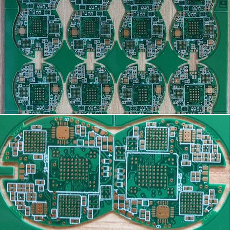
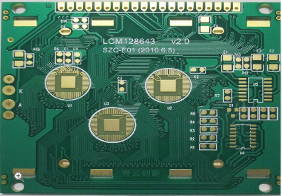
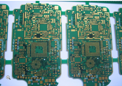
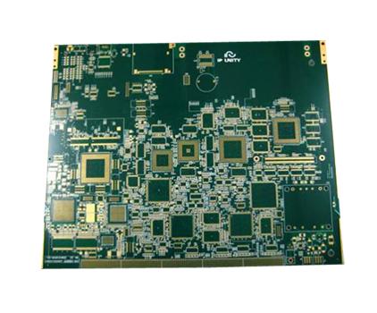
High Performance Video Network Sending Card PCB Design for Seamless Data Transmission Solutions
In today's fast-paced digital landscape, the demand for high-quality video transmission has skyrocketed, driven by applications ranging from live broadcasting and video conferencing to digital signage and surveillance systems. At the heart of these systems lies the High Performance Video Network Sending Card, a critical component that ensures seamless data transmission across networks. This article delves into the intricate PCB (Printed Circuit Board) design of such cards, exploring how advanced engineering enables reliable, high-speed video streaming with minimal latency. By understanding the design principles, readers can appreciate the technological innovations that power modern visual communication, making it an essential topic for engineers, tech enthusiasts, and industry professionals alike.
Signal Integrity and EMI Management
Signal integrity is paramount in high-performance video network sending cards, as any degradation can lead to artifacts, lag, or complete data loss in video streams. The PCB design must account for factors like impedance matching, crosstalk, and signal attenuation, especially with high-frequency data signals common in video transmission. Designers employ techniques such as controlled impedance routing and differential signaling to maintain clean signal paths, ensuring that video data remains intact from source to destination. This involves precise calculations of trace widths and spacing, tailored to the specific materials and layer stack-up of the PCB.
Electromagnetic interference (EMI) poses another significant challenge, as it can disrupt both the card's operation and nearby electronic devices. To mitigate EMI, the PCB layout incorporates shielding, ground planes, and careful component placement. For instance, high-speed components like processors and memory are isolated from analog sections, and vias are used to create Faraday cages around sensitive areas. Additionally, compliance with international standards, such as FCC or CE regulations, requires thorough testing and simulation during the design phase to identify and address potential EMI hotspots before production.
Power Distribution and Thermal Management
A stable power supply is crucial for the reliable operation of a video network sending card, as voltage fluctuations can cause data corruption or hardware failures. The PCB design includes a robust power distribution network (PDN) with multiple voltage rails to support various components, such as FPGAs, network interfaces, and memory chips. This involves using dedicated power planes, decoupling capacitors, and voltage regulators placed close to high-current devices to minimize noise and ensure consistent performance. Simulations, like power integrity analysis, help optimize the PDN by predicting voltage drops and current densities under different load conditions.
Thermal management is equally important, as high-power components generate heat that can degrade performance or shorten the card's lifespan. The PCB layout integrates heat sinks, thermal vias, and copper pours to dissipate heat efficiently. In some designs, active cooling methods like fans or liquid cooling systems are incorporated, but the PCB itself must facilitate heat transfer away from critical areas. Material selection, such as using high-temperature substrates, also plays a role in maintaining operational stability during prolonged use in demanding environments.
High-Speed Networking Interfaces
Video network sending cards rely on high-speed interfaces to transmit data over networks, with Ethernet being the most common standard. The PCB design must support gigabit or even 10-gigabit Ethernet ports, which require careful routing of differential pairs to maintain signal integrity. This includes minimizing trace lengths, avoiding sharp bends, and ensuring proper termination to prevent reflections. Designers often use simulation tools to model the behavior of these high-speed signals, adjusting the layout to meet timing and noise margins specified by protocols like IEEE 802.3.
Beyond Ethernet, many cards incorporate additional interfaces such as HDMI, DisplayPort, or fiber optic connections for versatile video input and output. Each interface has its own PCB design considerations; for example, HDMI signals need shielding and impedance control to handle high-resolution video, while fiber optics require precise alignment of optical components. The integration of these interfaces into a single PCB demands a modular approach, where separate sections are optimized for their specific functions while maintaining overall system coherence and minimizing interference between different signal types.
Component Selection and Layout Optimization
Selecting the right components is a foundational step in PCB design for video network sending cards, as it directly impacts performance, cost, and reliability. Key components include high-speed processors (e.g., FPGAs or ASICs), memory modules (such as DDR SDRAM), and network controllers, all of which must be chosen based on bandwidth requirements and power consumption. The design process involves evaluating datasheets, considering supply chain availability, and ensuring compatibility with other system elements. For instance, using low-power components can reduce thermal load, while high-quality connectors enhance durability in industrial applications.
Once components are selected, their placement on the PCB is optimized to shorten signal paths, reduce parasitic effects, and facilitate manufacturing. This includes grouping related components together, such as placing memory close to the processor to minimize latency, and orienting parts to avoid obstructions in critical traces. Automated placement tools aid in this process, but manual adjustments are often necessary to address unique constraints. Additionally, the layout must account for mechanical factors, like board size and mounting points, to ensure the card fits seamlessly into end-user systems without compromising performance.
Testing and Validation for Real-World Reliability
Rigorous testing is essential to validate the PCB design for high-performance video network sending cards, as real-world conditions can reveal issues not apparent in simulations. This begins with prototype testing, where boards are subjected to functional checks, signal integrity measurements, and environmental stress tests. Tools like oscilloscopes and network analyzers are used to verify that data transmission meets specifications, such as low bit error rates and consistent frame rates. Any deviations are addressed through iterative design revisions, ensuring that the final product delivers seamless video streaming under various network loads.
Long-term reliability is another critical aspect, particularly for cards deployed in 24/7 operations like broadcast studios or security systems. Accelerated life testing, such as thermal cycling and vibration tests, helps identify potential failure points, such as solder joint cracks or component degradation. Furthermore, compliance with industry standards, including RoHS for environmental safety and UL for electrical safety, requires thorough documentation and certification. By incorporating feedback from these tests into the design process, manufacturers can produce robust PCBs that uphold the promise of seamless data transmission in diverse applications.
REPORT


