-
 Agriculture
-
 Health-Care
-
 Environment
-
 Construction-Real-Estate
-
 Tools-Hardware
-
 Home-Garden
-
 Furniture
-
 Luggage-Bags-Cases
-
 Medical-devices-Supplies
-
 Gifts-Crafts
-
 Sports-Entertainment
-
 Food-Beverage
-
 Vehicles-Transportation
-
 Power-Transmission
-
 Material-Handling
-
 Renewable-Energy
-
 Safety
-
 Testing-Instrument-Equipment
-
 Construction-Building-Machinery
-
 Pet-Supplies
-
 Personal-Care-Household-Cleaning
-
 Vehicle-Accessories-Electronics-Tools
-
 School-Office-Supplies
-
 Packaging-Printing
-
 Mother-Kids-Toys
-
 Business-Services
-
 Commercial-Equipment-Machinery
-
 Apparel-Accessories
-
 Security
-
 Shoes-Accessories
-
 Vehicle-Parts-Accessories
-
 Jewelry-Eyewear-Watches-Accessories
-
 Lights-Lighting
-
 Fabric-Textile-Raw-Material
-
 Fabrication-Services
-
 Industrial-Machinery
-
 Consumer-Electronics
-
 Electrical-Equipment-Supplies
-
 Electronic-Components-Accessories-Telecommunications
-
 Home-Appliances
-
 Beauty
-
 Chemicals
-
 Rubber-Plastics
-
 Metals-Alloys
- Masonry Materials
- Curtain Walls & Accessories
- Earthwork Products
- Fireproofing Materials
- Heat Insulation Materials
- Plastic Building Materials
- Building Boards
- Soundproofing Materials
- Timber
- Waterproofing Materials
- Balustrades & Handrails
- Bathroom & Kitchen
- Flooring & Accessories
- Tiles & Accessories
- Door, Window & Accessories
- Fireplaces & Stoves
- Floor Heating Systems & Parts
- Stairs & Stair Parts
- Ceilings
- Elevators & Escalators
- Stone
- Countertops, Vanity Tops & Table Tops
- Mosaics
- Metal Building Materials
- Multifunctional Materials
- Ladders & Scaffoldings
- Mouldings
- Corner Guards
- Decorative Films
- Formwork
- Building & Industrial Glass
- Other Construction & Real Estate
- Wallpapers/Wall panels
- HVAC System & Parts
- Outdoor Facilities
- Prefabricated Buildings
- Festive & Party Supplies
- Bathroom Products
- Household Sundries
- Rain Gear
- Garden Supplies
- Household Cleaning Tools & Accessories
- Lighters & Smoking Accessories
- Home Storage & Organization
- Household Scales
- Smart Home Improvement
- Home Textiles
- Kitchenware
- Drinkware & Accessories
- Dinnerware, Coffee & Wine
- Home Decor
- Golf
- Fitness & Body Building
- Amusement Park Facilities
- Billiards, Board Game,Coin Operated Games
- Musical Instruments
- Outdoor Affordable Luxury Sports
- Camping & Hiking
- Fishing
- Sports Safety&Rehabilitation
- Ball Sports Equipments
- Water Sports
- Winter Sports
- Luxury Travel Equipments
- Sports Shoes, Bags & Accessories
- Cycling
- Other Sports & Entertainment Products
- Artificial Grass&Sports Flooring&Sports Court Equipment
- Scooters
- Food Ingredients
- Honey & Honey Products
- Snacks
- Nuts & Kernels
- Seafood
- Plant & Animal Oil
- Beverages
- Fruit & Vegetable Products
- Frog & Escargot
- Bean Products
- Egg Products
- Dairy Products
- Seasonings & Condiments
- Canned Food
- Instant Food
- Baked Goods
- Other Food & Beverage
- Meat & Poultry
- Confectionery
- Grain Products
- Feminie Care
- Hair Care & Styling
- Body Care
- Hands & Feet Care
- Hygiene Products
- Men's Grooming
- Laundry Cleaning Supplies
- Travel Size & Gift Sets
- Room Deodorizers
- Other Personal Care Products
- Pest Control Products
- Special Household Cleaning
- Floor Cleaning
- Kitchen & Bathroom Cleaning
- Oral Care
- Bath Supplies
- Yellow Pages
- Correction Supplies
- Office Binding Supplies
- Office Cutting Supplies
- Board Erasers
- Office Adhesives & Tapes
- Education Supplies
- Pencil Cases & Bags
- Notebooks & Writing Pads
- File Folder Accessories
- Calendars
- Writing Accessories
- Commercial Office Supplies
- Pencil Sharpeners
- Pens
- Letter Pad/Paper
- Paper Envelopes
- Desk Organizers
- Pencils
- Markers & Highlighters
- Filing Products
- Art Supplies
- Easels
- Badge Holder & Accessories
- Office Paper
- Printer Supplies
- Book Covers
- Other Office & School Supplies
- Stationery Set
- Boards
- Clipboards
- Stamps
- Drafting Supplies
- Stencils
- Electronic Dictionary
- Books
- Map
- Magazines
- Calculators
- Baby & Toddler Toys
- Educational Toys
- Classic Toys
- Dress Up & Pretend Play
- Toy Vehicle
- Stuffed Animals & Plush Toys
- Outdoor Toys & Structures
- Balloons & Accessories
- Baby Food
- Children's Clothing
- Baby Supplies & Products
- Maternity Clothes
- Kids Shoes
- Baby Care
- Novelty & Gag Toys
- Dolls & Accessories
- Puzzle & Games
- Blocks & Model Building Toys
- Toddler Clothing
- Baby Clothing
- Kids' Luggage & Bags
- Arts, Crafts & DIY Toys
- Action & Toy Figures
- Baby Appliances
- Hobbies & Models
- Remote Control Toys
- Promotional Toys
- Pregnancy & Maternity
- Hygiene Products
- Kid's Textile&Bedding
- Novelty & Special Use
- Toy Weapons
- Baby Gifts
- Baby Storage & Organization
- Auto Drive Systems
- ATV/UTV Parts & Accessories
- Marine Parts & Accessories
- Other Auto Parts
- Trailer Parts & Accessories
- Auto Transmission Systems
- Train Parts & Accessories
- Universal Parts
- Railway Parts & Accessories
- Auto Brake Systems
- Aviation Parts & Accessories
- Truck Parts & Accessories
- Auto Suspension Systems
- Auto Lighting Systems
- New Energy Vehicle Parts & Accessories
- Auto Steering Systems
- Wheels, Tires & Accessories
- Bus Parts & Accessories
- Auto Performance Parts
- Cooling System
- Go-Kart & Kart Racer Parts & Accessories
- Air Conditioning Systems
- Heavy Duty Vehicle Parts & Accessories
- Auto Electrical Systems
- Auto Body Systems
- Auto Engine Systems
- Container Parts & Accessories
- Motorcycle Parts & Accessories
- Refrigeration & Heat Exchange Equipment
- Machine Tool Equipment
- Food & Beverage Machinery
- Agricultural Machinery & Equipment
- Apparel & Textile Machinery
- Chemical Machinery
- Packaging Machines
- Paper Production Machinery
- Plastic & Rubber Processing Machinery
- Industrial Robots
- Electronic Products Machinery
- Metal & Metallurgy Machinery
- Woodworking Machinery
- Home Product Manufacturing Machinery
- Machinery Accessories
- Environmental Machinery
- Machinery Service
- Electrical Equipment Manufacturing Machinery
- Industrial Compressors & Parts
- Tobacco & Cigarette Machinery
- Production Line
- Used Industrial Machinery
- Electronics Production Machinery
- Other Machinery & Industrial Equipment
- Camera, Photo & Accessories
- Portable Audio, Video & Accessories
- Television, Home Audio, Video & Accessories
- Video Games & Accessories
- Mobile Phone & Accessories
- Electronic Publications
- Earphone & Headphone & Accessories
- Speakers & Accessories
- Smart Electronics
- TV Receivers & Accessories
- Mobile Phone & Computer Repair Parts
- Chargers, Batteries & Power Supplies
- Used Electronics
- VR, AR, MR Hardware & Software
- Projectors & Presentation Equipments
- Other Consumer Electronics
- Cables & Commonly Used Accessories
- Computer Hardware & Software
- Displays, Signage and Optoelectronics
- Discrete Semiconductors
- Wireless & IoT Module and Products
- Telecommunications
- Connectors, Terminals & Accessories
- Development Boards, Electronic Modules and Kits
- Circuit Protection
- Sensors
- Isolators
- Audio Components and Products
- Integrated Circuits
- Power Supplies
- Relays
- RF, Microwave and RFID
- Electronic Accessories & Supplies
- Passive Components
- PCB & PCBA
- Air Quality Appliances
- Home Appliance Parts
- Heating & Cooling Appliances
- Small Kitchen Appliances
- Laundry Appliances
- Water Heaters
- Water Treatment Appliances
- Refrigerators & Freezers
- Personal Care & Beauty Appliances
- Major Kitchen Appliances
- Cleaning Appliances
- Second-hand Appliances
- Smart Home Appliances
- Other Home Appliances
- Energy Chemicals
- Inorganic Chemicals
- Basic Organic Chemicals
- Agrochemicals
- Admixture & Additives
- Catalysts & Chemical Auxiliary Agents
- Pigments & Dyestuff
- Coating & Paint
- Daily Chemicals
- Polymer
- Organic Intermediate
- Adhesives & Sealants
- Chemical Waste
- Biological Chemical Products
- Surface Treatment Chemicals
- Painting & Coating
- Chemical Reagents
- Flavor & Fragrance
- Non-Explosive Demolition Agents
- Other Chemicals
- Custom Chemical Services
Mastering HDI PCB Design Techniques For Superior Electrical Performance Thermal Management And Miniaturization In Demanding Electronic Applications
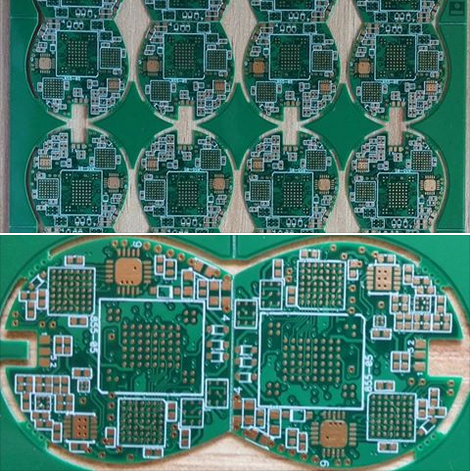
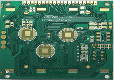
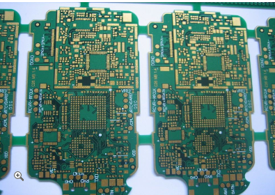
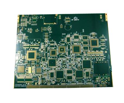
In today's rapidly evolving electronics industry, the demand for high-performance, compact, and reliable devices has never been greater. From smartphones and medical implants to automotive systems and aerospace technology, engineers face the constant challenge of packing more functionality into smaller spaces while ensuring optimal electrical performance and thermal stability. This is where High-Density Interconnect (HDI) printed circuit board (PCB) design emerges as a critical enabler. Mastering HDI PCB design techniques is no longer a niche skill but a fundamental requirement for success in demanding electronic applications. By leveraging advanced methodologies, designers can achieve superior signal integrity, efficient heat dissipation, and significant miniaturization, pushing the boundaries of what's possible in modern electronics. This article delves into the core aspects of HDI PCB design, providing a comprehensive guide to harnessing its full potential for groundbreaking innovations.
Enhancing Electrical Performance through Advanced HDI Strategies
The electrical performance of a PCB is paramount in high-speed and high-frequency applications, where signal integrity can make or break a device's functionality. HDI techniques play a pivotal role in optimizing this aspect by minimizing signal loss, reducing electromagnetic interference (EMI), and improving power integrity. One key approach involves the use of microvias and blind/buried vias, which allow for shorter and more direct routing paths between components. This reduction in interconnect length decreases parasitic capacitance and inductance, leading to faster signal transmission speeds and lower attenuation. For instance, in 5G communication systems, where data rates exceed several gigabits per second, HDI design ensures that signals remain clean and stable, preventing errors and data corruption.
Another critical factor is the implementation of controlled impedance routing and careful stack-up planning. HDI PCBs often incorporate multiple layers with precise dielectric materials to maintain consistent impedance across transmission lines. By utilizing simulation tools during the design phase, engineers can model and adjust trace widths, spacing, and layer arrangements to match target impedance values, such as 50 or 100 ohms. This is especially vital in differential pair routing for interfaces like USB-C or PCIe, where imbalances can cause signal reflections and jitter. Additionally, proper grounding schemes and via shielding in HDI layouts help contain EMI, reducing cross-talk between adjacent traces and minimizing radiation that could interfere with other electronic components. Through these methods, HDI design not only supports higher bandwidths but also enhances the overall reliability of electronic systems in sensitive environments like medical diagnostics or autonomous vehicles.
Achieving Effective Thermal Management in Dense Layouts
As electronic devices become more powerful and compact, managing heat dissipation becomes increasingly challenging. Excessive temperatures can lead to component failure, reduced lifespan, and performance degradation, making thermal management a cornerstone of HDI PCB design. HDI boards, with their high component density, require innovative strategies to disperse heat efficiently. One effective technique is the integration of thermal vias, which are plated holes filled with conductive material that transfer heat from hot spots, such as processors or power ICs, to inner ground planes or external heat sinks. By strategically placing these vias under component pads, designers can create low-resistance thermal paths that prevent localized overheating, ensuring stable operation even under heavy loads in applications like servers or gaming consoles.
Beyond vias, material selection plays a crucial role in thermal performance. HDI designs often utilize substrates with high thermal conductivity, such as metal-core PCBs or ceramics, which excel at spreading heat across the board. For example, in LED lighting or power converters, these materials help maintain junction temperatures within safe limits, prolonging device longevity. Furthermore, simulation-driven design allows engineers to perform thermal analysis early in the process, identifying potential hotspots and optimizing component placement and copper pours for better heat distribution. Coupled with adequate airflow planning in the end-product enclosure, these HDI techniques enable robust thermal management that supports continuous operation in extreme conditions, from industrial automation to outdoor telecommunications equipment.
Driving Miniaturization with High-Density Layout Innovations
The push for smaller, lighter, and more portable electronics has made miniaturization a primary goal in PCB design, and HDI technology is at the forefront of this trend. By enabling higher wiring density and finer features, HDI allows designers to shrink board sizes without sacrificing functionality. Key to this is the use of laser-drilled microvias, which have diameters as small as 50 micrometers, permitting tighter pitch components like ball grid arrays (BGAs) and chip-scale packages (CSPs). This capability is essential in wearable devices, such as smartwatches or hearing aids, where space is severely limited, yet performance requirements are high. With HDI, multiple layers can be interconnected in a compact area, reducing the overall footprint and enabling sleeker product designs.
Another aspect of miniaturization in HDI involves advanced manufacturing processes like sequential lamination and any-layer via technology. These methods allow for the creation of complex, multilayer boards with interconnections that span across various layers, eliminating the need for through-hole vias that consume valuable real estate. For instance, in mobile phones, HDI design supports the integration of cameras, sensors, and processors into a single, densely packed board, driving the trend toward bezel-less displays and enhanced features. Moreover, by reducing the length of electrical paths, miniaturization through HDI also contributes to improved signal speed and lower power consumption, as seen in IoT devices that rely on long battery life. Ultimately, mastering these layout innovations empowers engineers to meet the growing consumer demand for compact, high-performance electronics in markets ranging from consumer gadgets to military applications.
Integrating Design for Manufacturing and Reliability
While HDI techniques offer numerous benefits, their successful implementation hinges on designing for manufacturability (DFM) and reliability (DFR). Overlooking these aspects can lead to production delays, increased costs, and field failures. DFM in HDI involves adhering to manufacturer capabilities, such as minimum trace widths, via sizes, and layer alignment tolerances. For example, when using microvias, designers must account for aspect ratios and via-in-pad structures to ensure reliable plating and avoid voids during assembly. Collaboration with PCB fabricators early in the design phase helps identify potential issues, such as acid traps or uneven copper distribution, which could compromise board integrity in high-reliability applications like automotive control systems.
On the reliability front, HDI designs must address mechanical stress, thermal cycling, and environmental factors. Techniques like via tenting and filleting can strengthen via structures, reducing the risk of cracking under vibration or temperature fluctuations. In harsh environments, such as aerospace or marine electronics, additional protective coatings and conformal masks may be incorporated to guard against moisture, corrosion, and contaminants. Furthermore, thorough testing protocols, including automated optical inspection (AOI) and thermal shock tests, validate the durability of HDI boards. By integrating DFM and DFR principles, designers can achieve a balance between performance and practicality, ensuring that HDI-based products not only meet specifications but also withstand the rigors of real-world use, thereby enhancing customer satisfaction and brand reputation.
REPORT


