-
 Agriculture
-
 Health-Care
-
 Environment
-
 Construction-Real-Estate
-
 Tools-Hardware
-
 Home-Garden
-
 Furniture
-
 Luggage-Bags-Cases
-
 Medical-devices-Supplies
-
 Gifts-Crafts
-
 Sports-Entertainment
-
 Food-Beverage
-
 Vehicles-Transportation
-
 Power-Transmission
-
 Material-Handling
-
 Renewable-Energy
-
 Safety
-
 Testing-Instrument-Equipment
-
 Construction-Building-Machinery
-
 Pet-Supplies
-
 Personal-Care-Household-Cleaning
-
 Vehicle-Accessories-Electronics-Tools
-
 School-Office-Supplies
-
 Packaging-Printing
-
 Mother-Kids-Toys
-
 Business-Services
-
 Commercial-Equipment-Machinery
-
 Apparel-Accessories
-
 Security
-
 Shoes-Accessories
-
 Vehicle-Parts-Accessories
-
 Jewelry-Eyewear-Watches-Accessories
-
 Lights-Lighting
-
 Fabric-Textile-Raw-Material
-
 Fabrication-Services
-
 Industrial-Machinery
-
 Consumer-Electronics
-
 Electrical-Equipment-Supplies
-
 Electronic-Components-Accessories-Telecommunications
-
 Home-Appliances
-
 Beauty
-
 Chemicals
-
 Rubber-Plastics
-
 Metals-Alloys
- Masonry Materials
- Curtain Walls & Accessories
- Earthwork Products
- Fireproofing Materials
- Heat Insulation Materials
- Plastic Building Materials
- Building Boards
- Soundproofing Materials
- Timber
- Waterproofing Materials
- Balustrades & Handrails
- Bathroom & Kitchen
- Flooring & Accessories
- Tiles & Accessories
- Door, Window & Accessories
- Fireplaces & Stoves
- Floor Heating Systems & Parts
- Stairs & Stair Parts
- Ceilings
- Elevators & Escalators
- Stone
- Countertops, Vanity Tops & Table Tops
- Mosaics
- Metal Building Materials
- Multifunctional Materials
- Ladders & Scaffoldings
- Mouldings
- Corner Guards
- Decorative Films
- Formwork
- Building & Industrial Glass
- Other Construction & Real Estate
- Wallpapers/Wall panels
- HVAC System & Parts
- Outdoor Facilities
- Prefabricated Buildings
- Festive & Party Supplies
- Bathroom Products
- Household Sundries
- Rain Gear
- Garden Supplies
- Household Cleaning Tools & Accessories
- Lighters & Smoking Accessories
- Home Storage & Organization
- Household Scales
- Smart Home Improvement
- Home Textiles
- Kitchenware
- Drinkware & Accessories
- Dinnerware, Coffee & Wine
- Home Decor
- Golf
- Fitness & Body Building
- Amusement Park Facilities
- Billiards, Board Game,Coin Operated Games
- Musical Instruments
- Outdoor Affordable Luxury Sports
- Camping & Hiking
- Fishing
- Sports Safety&Rehabilitation
- Ball Sports Equipments
- Water Sports
- Winter Sports
- Luxury Travel Equipments
- Sports Shoes, Bags & Accessories
- Cycling
- Other Sports & Entertainment Products
- Artificial Grass&Sports Flooring&Sports Court Equipment
- Scooters
- Food Ingredients
- Honey & Honey Products
- Snacks
- Nuts & Kernels
- Seafood
- Plant & Animal Oil
- Beverages
- Fruit & Vegetable Products
- Frog & Escargot
- Bean Products
- Egg Products
- Dairy Products
- Seasonings & Condiments
- Canned Food
- Instant Food
- Baked Goods
- Other Food & Beverage
- Meat & Poultry
- Confectionery
- Grain Products
- Feminie Care
- Hair Care & Styling
- Body Care
- Hands & Feet Care
- Hygiene Products
- Men's Grooming
- Laundry Cleaning Supplies
- Travel Size & Gift Sets
- Room Deodorizers
- Other Personal Care Products
- Pest Control Products
- Special Household Cleaning
- Floor Cleaning
- Kitchen & Bathroom Cleaning
- Oral Care
- Bath Supplies
- Yellow Pages
- Correction Supplies
- Office Binding Supplies
- Office Cutting Supplies
- Board Erasers
- Office Adhesives & Tapes
- Education Supplies
- Pencil Cases & Bags
- Notebooks & Writing Pads
- File Folder Accessories
- Calendars
- Writing Accessories
- Commercial Office Supplies
- Pencil Sharpeners
- Pens
- Letter Pad/Paper
- Paper Envelopes
- Desk Organizers
- Pencils
- Markers & Highlighters
- Filing Products
- Art Supplies
- Easels
- Badge Holder & Accessories
- Office Paper
- Printer Supplies
- Book Covers
- Other Office & School Supplies
- Stationery Set
- Boards
- Clipboards
- Stamps
- Drafting Supplies
- Stencils
- Electronic Dictionary
- Books
- Map
- Magazines
- Calculators
- Baby & Toddler Toys
- Educational Toys
- Classic Toys
- Dress Up & Pretend Play
- Toy Vehicle
- Stuffed Animals & Plush Toys
- Outdoor Toys & Structures
- Balloons & Accessories
- Baby Food
- Children's Clothing
- Baby Supplies & Products
- Maternity Clothes
- Kids Shoes
- Baby Care
- Novelty & Gag Toys
- Dolls & Accessories
- Puzzle & Games
- Blocks & Model Building Toys
- Toddler Clothing
- Baby Clothing
- Kids' Luggage & Bags
- Arts, Crafts & DIY Toys
- Action & Toy Figures
- Baby Appliances
- Hobbies & Models
- Remote Control Toys
- Promotional Toys
- Pregnancy & Maternity
- Hygiene Products
- Kid's Textile&Bedding
- Novelty & Special Use
- Toy Weapons
- Baby Gifts
- Baby Storage & Organization
- Auto Drive Systems
- ATV/UTV Parts & Accessories
- Marine Parts & Accessories
- Other Auto Parts
- Trailer Parts & Accessories
- Auto Transmission Systems
- Train Parts & Accessories
- Universal Parts
- Railway Parts & Accessories
- Auto Brake Systems
- Aviation Parts & Accessories
- Truck Parts & Accessories
- Auto Suspension Systems
- Auto Lighting Systems
- New Energy Vehicle Parts & Accessories
- Auto Steering Systems
- Wheels, Tires & Accessories
- Bus Parts & Accessories
- Auto Performance Parts
- Cooling System
- Go-Kart & Kart Racer Parts & Accessories
- Air Conditioning Systems
- Heavy Duty Vehicle Parts & Accessories
- Auto Electrical Systems
- Auto Body Systems
- Auto Engine Systems
- Container Parts & Accessories
- Motorcycle Parts & Accessories
- Refrigeration & Heat Exchange Equipment
- Machine Tool Equipment
- Food & Beverage Machinery
- Agricultural Machinery & Equipment
- Apparel & Textile Machinery
- Chemical Machinery
- Packaging Machines
- Paper Production Machinery
- Plastic & Rubber Processing Machinery
- Industrial Robots
- Electronic Products Machinery
- Metal & Metallurgy Machinery
- Woodworking Machinery
- Home Product Manufacturing Machinery
- Machinery Accessories
- Environmental Machinery
- Machinery Service
- Electrical Equipment Manufacturing Machinery
- Industrial Compressors & Parts
- Tobacco & Cigarette Machinery
- Production Line
- Used Industrial Machinery
- Electronics Production Machinery
- Other Machinery & Industrial Equipment
- Camera, Photo & Accessories
- Portable Audio, Video & Accessories
- Television, Home Audio, Video & Accessories
- Video Games & Accessories
- Mobile Phone & Accessories
- Electronic Publications
- Earphone & Headphone & Accessories
- Speakers & Accessories
- Smart Electronics
- TV Receivers & Accessories
- Mobile Phone & Computer Repair Parts
- Chargers, Batteries & Power Supplies
- Used Electronics
- VR, AR, MR Hardware & Software
- Projectors & Presentation Equipments
- Other Consumer Electronics
- Cables & Commonly Used Accessories
- Computer Hardware & Software
- Displays, Signage and Optoelectronics
- Discrete Semiconductors
- Wireless & IoT Module and Products
- Telecommunications
- Connectors, Terminals & Accessories
- Development Boards, Electronic Modules and Kits
- Circuit Protection
- Sensors
- Isolators
- Audio Components and Products
- Integrated Circuits
- Power Supplies
- Relays
- RF, Microwave and RFID
- Electronic Accessories & Supplies
- Passive Components
- PCB & PCBA
- Air Quality Appliances
- Home Appliance Parts
- Heating & Cooling Appliances
- Small Kitchen Appliances
- Laundry Appliances
- Water Heaters
- Water Treatment Appliances
- Refrigerators & Freezers
- Personal Care & Beauty Appliances
- Major Kitchen Appliances
- Cleaning Appliances
- Second-hand Appliances
- Smart Home Appliances
- Other Home Appliances
- Energy Chemicals
- Inorganic Chemicals
- Basic Organic Chemicals
- Agrochemicals
- Admixture & Additives
- Catalysts & Chemical Auxiliary Agents
- Pigments & Dyestuff
- Coating & Paint
- Daily Chemicals
- Polymer
- Organic Intermediate
- Adhesives & Sealants
- Chemical Waste
- Biological Chemical Products
- Surface Treatment Chemicals
- Painting & Coating
- Chemical Reagents
- Flavor & Fragrance
- Non-Explosive Demolition Agents
- Other Chemicals
- Custom Chemical Services
Multi Layer PCB Fabrication Step By Step From Inner Layer Imaging To Lamination Drilling And Plating For Flawless Circuit Board Production
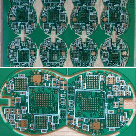
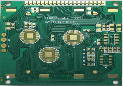
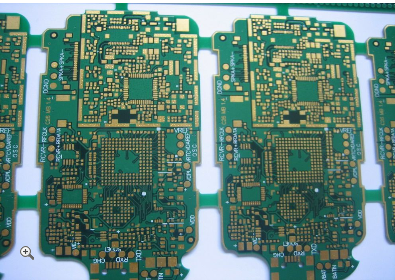
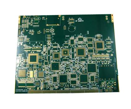
In the intricate world of electronics, multi-layer printed circuit boards (PCBs) stand as the backbone of modern devices, enabling the complex functionality we rely on daily. From smartphones to medical equipment, these boards facilitate the seamless flow of electrical signals across multiple layers, packed into a compact form. The fabrication of multi-layer PCBs is a meticulous process that demands precision at every stage to ensure flawless performance. This article delves into the step-by-step journey from inner layer imaging to lamination, drilling, and plating, highlighting the critical techniques that transform raw materials into reliable circuit boards. By understanding this process, readers can appreciate the engineering marvel behind everyday technology and the importance of quality control in production.
Inner Layer Imaging and Etching
The fabrication of a multi-layer PCB begins with the inner layers, which form the core of the board. These layers are typically made from copper-clad laminate sheets, composed of a dielectric material like FR-4 coated with a thin layer of copper. The first step involves cleaning the laminate to remove any contaminants that could interfere with the imaging process. This is crucial because even minor impurities can lead to defects in the final circuit, compromising the board's integrity. Once cleaned, the surface is treated to enhance adhesion for the subsequent photoresist application, ensuring a uniform coating.
Next, the inner layer imaging process commences, where the circuit pattern is transferred onto the copper surface. A photosensitive dry film or liquid photoresist is applied to the laminate, and it is exposed to ultraviolet light through a photomask that contains the desired circuit design. The exposed areas of the photoresist harden, while the unexposed portions remain soluble. This step requires precise alignment and exposure control to accurately replicate the intricate traces and pads of the design. After exposure, the board undergoes development, where a chemical solution washes away the unexposed photoresist, revealing the copper that will be etched away. The etching process then uses an acidic solution, such as ammonium persulfate or ferric chloride, to remove the unprotected copper, leaving behind the circuit pattern. Finally, the remaining photoresist is stripped, and the inner layers are inspected for any defects using automated optical inspection (AOI) systems to ensure they meet the design specifications before moving to the next stage.
Oxide Treatment and Lamination
After the inner layers are etched and inspected, they undergo an oxide treatment to improve adhesion during lamination. This involves applying a chemical coating, typically black or brown oxide, to the copper surfaces. The oxide layer creates a rough texture that enhances the bond between the inner layers and the prepreg (pre-impregnated) material used in lamination. This step is vital for preventing delamination—a common failure where layers separate under thermal or mechanical stress—ensuring the board's long-term reliability. The treated layers are then dried and stored in a controlled environment to avoid contamination before lamination.
The lamination process assembles the multiple layers into a single, solid board. It starts with stacking the inner layers alternating with sheets of prepreg, which is a fiberglass material impregnated with partially cured epoxy resin. The outer layers, usually copper foils, are placed on the top and bottom of the stack. This stack is then placed into a lamination press, where heat and pressure are applied. The heat melts the resin in the prepreg, allowing it to flow and fill any gaps, while the pressure bonds the layers together. The temperature and pressure profiles are carefully controlled to ensure complete curing without voids or bubbles. Once laminated, the board is cooled slowly to relieve internal stresses, resulting in a robust, multi-layer structure. Post-lamination, the board may undergo edge trimming and inspection to verify layer alignment and bond quality, setting the stage for drilling and plating.
Drilling and Electroless Copper Plating
Drilling is a critical step that creates the holes, or vias, which electrically connect the different layers of the PCB. Using computer-controlled drill machines, precise holes are drilled through the laminated board based on the design files. The accuracy of this process is paramount, as misaligned holes can lead to open circuits or short circuits. Drill bits are selected based on the hole size and material, and they often wear out quickly due to the abrasive nature of the fiberglass, requiring frequent replacement to maintain precision. After drilling, the holes are deburred to remove any rough edges or debris, ensuring a clean surface for subsequent plating.
Following drilling, the board undergoes electroless copper plating to deposit a thin layer of copper onto the hole walls, establishing electrical connectivity between layers. This begins with a series of chemical treatments, including desmearing to remove resin residue from the drilling process and etching to roughen the hole surfaces for better adhesion. The board is then immersed in a catalytic solution that prepares it for copper deposition. In the electroless plating bath, a chemical reaction deposits a uniform copper layer—typically 0.5 to 1 micron thick—across the entire surface, including the holes. This initial layer is essential for conducting electricity during the subsequent electroplating step. Quality checks, such as cross-sectional analysis, are performed to ensure the plating is continuous and free of voids, which could cause interconnection failures in the final product.
Outer Layer Imaging and Electroplating
With the holes plated, the outer layers are prepared for imaging, similar to the inner layers. The board is cleaned and coated with a photoresist, then exposed to UV light through a photomask that defines the outer circuit patterns. After development, the exposed copper areas—where circuits will form—are ready for electroplating. This step builds upon the electroless copper layer, adding thickness to ensure durability and conductivity. The board is placed in an electroplating bath, where an electric current flows through the copper, depositing additional copper onto the patterned areas and hole walls. The thickness is carefully controlled, often reaching 25-30 microns, to meet the design requirements for current carrying capacity and mechanical strength.
After electroplating, a thin layer of tin may be applied as an etch resist to protect the copper circuits during the final etching phase. The remaining photoresist is then stripped, revealing the unprotected copper, which is etched away using a chemical solution. The tin resist is subsequently removed, leaving behind the precise outer circuit patterns. The board undergoes another round of inspection, including electrical testing to verify connectivity and isolation between circuits. Any defects, such as shorts or opens, are corrected at this stage to ensure the board functions as intended. Finally, surface finishes like HASL (Hot Air Solder Leveling) or ENIG (Electroless Nickel Immersion Gold) may be applied to protect the copper from oxidation and enhance solderability, completing the fabrication process for a flawless multi-layer PCB ready for assembly.
REPORT


