-
 Agriculture
-
 Health-Care
-
 Environment
-
 Construction-Real-Estate
-
 Tools-Hardware
-
 Home-Garden
-
 Furniture
-
 Luggage-Bags-Cases
-
 Medical-devices-Supplies
-
 Gifts-Crafts
-
 Sports-Entertainment
-
 Food-Beverage
-
 Vehicles-Transportation
-
 Power-Transmission
-
 Material-Handling
-
 Renewable-Energy
-
 Safety
-
 Testing-Instrument-Equipment
-
 Construction-Building-Machinery
-
 Pet-Supplies
-
 Personal-Care-Household-Cleaning
-
 Vehicle-Accessories-Electronics-Tools
-
 School-Office-Supplies
-
 Packaging-Printing
-
 Mother-Kids-Toys
-
 Business-Services
-
 Commercial-Equipment-Machinery
-
 Apparel-Accessories
-
 Security
-
 Shoes-Accessories
-
 Vehicle-Parts-Accessories
-
 Jewelry-Eyewear-Watches-Accessories
-
 Lights-Lighting
-
 Fabric-Textile-Raw-Material
-
 Fabrication-Services
-
 Industrial-Machinery
-
 Consumer-Electronics
-
 Electrical-Equipment-Supplies
-
 Electronic-Components-Accessories-Telecommunications
-
 Home-Appliances
-
 Beauty
-
 Chemicals
-
 Rubber-Plastics
-
 Metals-Alloys
- Masonry Materials
- Curtain Walls & Accessories
- Earthwork Products
- Fireproofing Materials
- Heat Insulation Materials
- Plastic Building Materials
- Building Boards
- Soundproofing Materials
- Timber
- Waterproofing Materials
- Balustrades & Handrails
- Bathroom & Kitchen
- Flooring & Accessories
- Tiles & Accessories
- Door, Window & Accessories
- Fireplaces & Stoves
- Floor Heating Systems & Parts
- Stairs & Stair Parts
- Ceilings
- Elevators & Escalators
- Stone
- Countertops, Vanity Tops & Table Tops
- Mosaics
- Metal Building Materials
- Multifunctional Materials
- Ladders & Scaffoldings
- Mouldings
- Corner Guards
- Decorative Films
- Formwork
- Building & Industrial Glass
- Other Construction & Real Estate
- Wallpapers/Wall panels
- HVAC System & Parts
- Outdoor Facilities
- Prefabricated Buildings
- Festive & Party Supplies
- Bathroom Products
- Household Sundries
- Rain Gear
- Garden Supplies
- Household Cleaning Tools & Accessories
- Lighters & Smoking Accessories
- Home Storage & Organization
- Household Scales
- Smart Home Improvement
- Home Textiles
- Kitchenware
- Drinkware & Accessories
- Dinnerware, Coffee & Wine
- Home Decor
- Golf
- Fitness & Body Building
- Amusement Park Facilities
- Billiards, Board Game,Coin Operated Games
- Musical Instruments
- Outdoor Affordable Luxury Sports
- Camping & Hiking
- Fishing
- Sports Safety&Rehabilitation
- Ball Sports Equipments
- Water Sports
- Winter Sports
- Luxury Travel Equipments
- Sports Shoes, Bags & Accessories
- Cycling
- Other Sports & Entertainment Products
- Artificial Grass&Sports Flooring&Sports Court Equipment
- Scooters
- Food Ingredients
- Honey & Honey Products
- Snacks
- Nuts & Kernels
- Seafood
- Plant & Animal Oil
- Beverages
- Fruit & Vegetable Products
- Frog & Escargot
- Bean Products
- Egg Products
- Dairy Products
- Seasonings & Condiments
- Canned Food
- Instant Food
- Baked Goods
- Other Food & Beverage
- Meat & Poultry
- Confectionery
- Grain Products
- Feminie Care
- Hair Care & Styling
- Body Care
- Hands & Feet Care
- Hygiene Products
- Men's Grooming
- Laundry Cleaning Supplies
- Travel Size & Gift Sets
- Room Deodorizers
- Other Personal Care Products
- Pest Control Products
- Special Household Cleaning
- Floor Cleaning
- Kitchen & Bathroom Cleaning
- Oral Care
- Bath Supplies
- Yellow Pages
- Correction Supplies
- Office Binding Supplies
- Office Cutting Supplies
- Board Erasers
- Office Adhesives & Tapes
- Education Supplies
- Pencil Cases & Bags
- Notebooks & Writing Pads
- File Folder Accessories
- Calendars
- Writing Accessories
- Commercial Office Supplies
- Pencil Sharpeners
- Pens
- Letter Pad/Paper
- Paper Envelopes
- Desk Organizers
- Pencils
- Markers & Highlighters
- Filing Products
- Art Supplies
- Easels
- Badge Holder & Accessories
- Office Paper
- Printer Supplies
- Book Covers
- Other Office & School Supplies
- Stationery Set
- Boards
- Clipboards
- Stamps
- Drafting Supplies
- Stencils
- Electronic Dictionary
- Books
- Map
- Magazines
- Calculators
- Baby & Toddler Toys
- Educational Toys
- Classic Toys
- Dress Up & Pretend Play
- Toy Vehicle
- Stuffed Animals & Plush Toys
- Outdoor Toys & Structures
- Balloons & Accessories
- Baby Food
- Children's Clothing
- Baby Supplies & Products
- Maternity Clothes
- Kids Shoes
- Baby Care
- Novelty & Gag Toys
- Dolls & Accessories
- Puzzle & Games
- Blocks & Model Building Toys
- Toddler Clothing
- Baby Clothing
- Kids' Luggage & Bags
- Arts, Crafts & DIY Toys
- Action & Toy Figures
- Baby Appliances
- Hobbies & Models
- Remote Control Toys
- Promotional Toys
- Pregnancy & Maternity
- Hygiene Products
- Kid's Textile&Bedding
- Novelty & Special Use
- Toy Weapons
- Baby Gifts
- Baby Storage & Organization
- Auto Drive Systems
- ATV/UTV Parts & Accessories
- Marine Parts & Accessories
- Other Auto Parts
- Trailer Parts & Accessories
- Auto Transmission Systems
- Train Parts & Accessories
- Universal Parts
- Railway Parts & Accessories
- Auto Brake Systems
- Aviation Parts & Accessories
- Truck Parts & Accessories
- Auto Suspension Systems
- Auto Lighting Systems
- New Energy Vehicle Parts & Accessories
- Auto Steering Systems
- Wheels, Tires & Accessories
- Bus Parts & Accessories
- Auto Performance Parts
- Cooling System
- Go-Kart & Kart Racer Parts & Accessories
- Air Conditioning Systems
- Heavy Duty Vehicle Parts & Accessories
- Auto Electrical Systems
- Auto Body Systems
- Auto Engine Systems
- Container Parts & Accessories
- Motorcycle Parts & Accessories
- Refrigeration & Heat Exchange Equipment
- Machine Tool Equipment
- Food & Beverage Machinery
- Agricultural Machinery & Equipment
- Apparel & Textile Machinery
- Chemical Machinery
- Packaging Machines
- Paper Production Machinery
- Plastic & Rubber Processing Machinery
- Industrial Robots
- Electronic Products Machinery
- Metal & Metallurgy Machinery
- Woodworking Machinery
- Home Product Manufacturing Machinery
- Machinery Accessories
- Environmental Machinery
- Machinery Service
- Electrical Equipment Manufacturing Machinery
- Industrial Compressors & Parts
- Tobacco & Cigarette Machinery
- Production Line
- Used Industrial Machinery
- Electronics Production Machinery
- Other Machinery & Industrial Equipment
- Camera, Photo & Accessories
- Portable Audio, Video & Accessories
- Television, Home Audio, Video & Accessories
- Video Games & Accessories
- Mobile Phone & Accessories
- Electronic Publications
- Earphone & Headphone & Accessories
- Speakers & Accessories
- Smart Electronics
- TV Receivers & Accessories
- Mobile Phone & Computer Repair Parts
- Chargers, Batteries & Power Supplies
- Used Electronics
- VR, AR, MR Hardware & Software
- Projectors & Presentation Equipments
- Other Consumer Electronics
- Cables & Commonly Used Accessories
- Computer Hardware & Software
- Displays, Signage and Optoelectronics
- Discrete Semiconductors
- Wireless & IoT Module and Products
- Telecommunications
- Connectors, Terminals & Accessories
- Development Boards, Electronic Modules and Kits
- Circuit Protection
- Sensors
- Isolators
- Audio Components and Products
- Integrated Circuits
- Power Supplies
- Relays
- RF, Microwave and RFID
- Electronic Accessories & Supplies
- Passive Components
- PCB & PCBA
- Air Quality Appliances
- Home Appliance Parts
- Heating & Cooling Appliances
- Small Kitchen Appliances
- Laundry Appliances
- Water Heaters
- Water Treatment Appliances
- Refrigerators & Freezers
- Personal Care & Beauty Appliances
- Major Kitchen Appliances
- Cleaning Appliances
- Second-hand Appliances
- Smart Home Appliances
- Other Home Appliances
- Energy Chemicals
- Inorganic Chemicals
- Basic Organic Chemicals
- Agrochemicals
- Admixture & Additives
- Catalysts & Chemical Auxiliary Agents
- Pigments & Dyestuff
- Coating & Paint
- Daily Chemicals
- Polymer
- Organic Intermediate
- Adhesives & Sealants
- Chemical Waste
- Biological Chemical Products
- Surface Treatment Chemicals
- Painting & Coating
- Chemical Reagents
- Flavor & Fragrance
- Non-Explosive Demolition Agents
- Other Chemicals
- Custom Chemical Services
Robust Flex PCB Designs for Medical Sensors Ensuring Long Term Performance and Accuracy
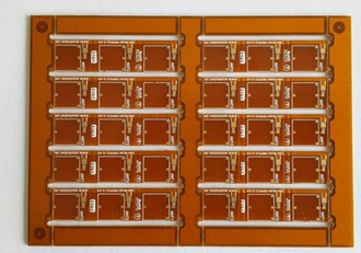
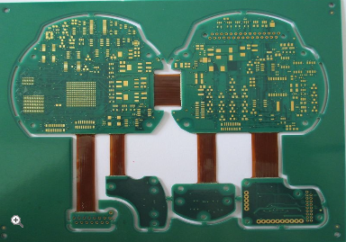
In the rapidly evolving landscape of medical technology, the demand for smaller, more reliable, and highly accurate diagnostic and monitoring devices is greater than ever. At the heart of many of these life-saving innovations lies a critical component: the flexible printed circuit board (Flex PCB). Unlike their rigid counterparts, flex PCBs can bend and conform to the unique shapes of the human body, enabling the development of wearable sensors, implantable devices, and minimally invasive surgical tools. However, the very environments that make these medical sensors so valuable—the human body and clinical settings—present immense challenges. Factors such as constant mechanical stress, exposure to moisture and chemicals, and the need for long-term, drift-free operation place extraordinary demands on the electronic foundations of these devices. This article delves into the principles and practices of creating robust flex PCB designs specifically for medical sensors, exploring how engineers ensure these delicate circuits can deliver sustained performance and unwavering accuracy over their entire operational lifespan, ultimately safeguarding patient health.
Material Selection for Durability and Biocompatibility
The foundation of any robust flex PCB design is the careful selection of materials. For medical sensors, this goes beyond simple electrical properties and delves into mechanical endurance and biological safety. The standard base material for flex circuits is polyimide, prized for its excellent thermal stability, high tensile strength, and resistance to chemicals. This is crucial for devices that may undergo repeated sterilization cycles using autoclaves or chemical agents. The thin copper layers used for traces must also be chosen with care, often requiring specific grades that resist work-hardening and cracking from constant flexing.
Furthermore, the selection of coverlays and solder mask is paramount. These protective layers shield the delicate copper traces from environmental hazards. In medical applications, they must be impervious to bodily fluids, sweat, and cleaning solvents. For implantable devices, the entire material stack must be biocompatible, meaning it does not elicit an adverse reaction from the body. This often involves using specialized, certified materials and conformal coatings that are non-toxic and stable within the harsh environment of the human body. The wrong material choice can lead to premature failure, signal degradation, or even harm to the patient, making this the first and most critical step in ensuring long-term robustness.
Mechanical Design and Layout for Stress Management
A flex PCB's ability to bend is its greatest asset, but uncontrolled bending is its primary failure mechanism. Therefore, a core aspect of robust design is managing mechanical stress. This begins with the layout of the circuit traces. Conductors should be routed perpendicular to the bend line whenever possible to distribute stress evenly across the trace's width. Sharp corners are avoided in favor of curved traces, which prevent stress concentration points that can lead to cracks. The use of tear-resistant substrates and adding stiffeners in areas where components are mounted or where connectors will be attached are common strategies to localize flexing to specific, designed regions.
Another critical consideration is the dynamic versus static flexing application. A sensor designed for a one-time bend during implantation (static flex) has different requirements than a wearable ECG patch that flexes with every patient movement (dynamic flex). For dynamic applications, designs must be even more conservative. This involves using thinner copper, wider traces, and a tighter bend radius calculation to ensure the PCB can withstand millions of flex cycles without failure. Finite Element Analysis (FEA) software is often employed to simulate mechanical stresses and identify potential weak points in the design before a prototype is ever built, saving time and preventing field failures.
Signal Integrity and Shielding for Uncompromised Accuracy
For a medical sensor, accuracy is non-negotiable. A robust design must ensure that the tiny electrical signals generated by physiological activity are captured faithfully without corruption from noise. This requires meticulous attention to signal integrity. Impedance control is critical for high-frequency signals, ensuring that traces are designed to a specific characteristic impedance to prevent signal reflections that can distort measurements. Proper grounding schemes, such as the use of ground planes, are essential to provide a stable reference and a low-impedance return path for currents.
Medical environments are notoriously electrically noisy, with interference from other medical equipment, wireless signals, and power lines. To protect sensitive analog signals, robust flex PCB designs incorporate effective shielding. This can be achieved through dedicated shield layers within a multi-layer flex stack-up or by using cross-hatched copper patterns. For very sensitive applications, a full Faraday cage might be implemented around critical circuit sections. Additionally, the placement of components is strategic; analog and digital sections are physically separated, and analog-to-digital converters (ADCs) are positioned as close as possible to the sensor element to minimize the length of vulnerable analog signal paths, thereby preserving the integrity of the data from source to processor.
Testing and Validation for Long-Term Reliability
The final pillar of creating a robust flex PCB for medical sensors is a rigorous regime of testing and validation. This process begins during prototyping and continues through manufacturing. Accelerated life testing is employed to simulate years of use in a condensed timeframe. Boards are subjected to repeated flexing cycles, thermal cycling (from cold to hot extremes), and humidity exposure to uncover any potential failure modes related to material fatigue or interfacial delamination.
Beyond mechanical testing, electrical performance is validated over these stress conditions. Parameters such as resistance, capacitance, and signal-to-noise ratio are monitored to ensure they remain within specification. For devices that require regulatory approval, such as those certified by the FDA or under ISO 13485, this testing must be thoroughly documented and reproducible. This comprehensive validation process provides the data-driven confidence that the flex PCB design will not only function correctly on day one but will continue to perform accurately and reliably throughout its intended service life, ensuring the safety and well-being of the patients who depend on it.
REPORT


